
Maxillary sinus bone graft method using the sinus lift drill (SLD) and hydraulic effect

a maxillary sinus bone and hydraulic effect technology, applied in the field of dental implants, can solve the problems of prolonging surgery, dentists having difficulty in implant installation, complicated dental implant surgery, etc., and achieve the effect of short surgery time and safe implant installation

Active Publication Date: 2011-12-27
SONG YOUNG WAN
View PDF6 Cites 9 Cited by
  • Summary
  • Abstract
  • Description
  • Claims
  • Application Information

AI Technical Summary

Benefits of technology

"The present invention provides a method for safely installing an implant in a short surgery time by using a sinus lift drill and hydraulic effect to penetrate a maxillary sinus floor without damaging the maxillary sinus membrane. The method includes steps of removing mucoperiosteum, penetrating the maxillary sinus floor, lifting the maxillary sinus membrane, and installing the implant in the same maxillary sinus floor. The graft used in the method is either a fluid substance or a non-fluid substance, and the method includes steps of injecting the graft using the hydraulic effect. The technical effects of the invention include simplifying the procedure, reducing surgery time, and ensuring the safety of the patient."

Problems solved by technology

However, in case of some dental patients, the structure of the oral cavity makes it difficult to perform the implant surgery, so that the dental implant surgery becomes complicated, or some dentists often decline to give such a patient medical treatment.
In particular, the dentist has difficulty in performing the implant installation in the case where a small amount of bone matrix remains in the posterior area near the maxillary sinus.
However, since the dentist cannot directly see the maxillary sinus membrane, he / she has to perform surgery very carefully, checking the membrane with X-ray images, which takes a lot of time, thereby prolonging the surgery, and in that the patient experiences severe discomfort due to the tapping during the surgery.
However, the method also has a problem in that the surgery itself is difficult to perform, and a larger mucoperiosteal flap should be provided, so that severe edema may occur after the surgery.
However, at the moment that the maxillary sinus membrane is completely bored by the rotation of the drill blades, the tips of the drill blades are brought into contact with the maxillary sinus membrane, damaging the membrane by tearing or rolling.
Therefore, the maxillary sinus elevation method using the drill is impossible to use.

Method used


Image

  • Maxillary sinus bone graft method using the sinus lift drill (SLD) and hydraulic effect
  • Maxillary sinus bone graft method using the sinus lift drill (SLD) and hydraulic effect
  • Maxillary sinus bone graft method using the sinus lift drill (SLD) and hydraulic effect

Examples


Embodiment Construction

[0023]Hereinafter, a maxillary sinus bone graft method using a sinus lift drill (SLD) and hydraulic effect according to the invention will be described more fully with reference to the accompanying drawings, in which exemplary embodiments thereof are shown.

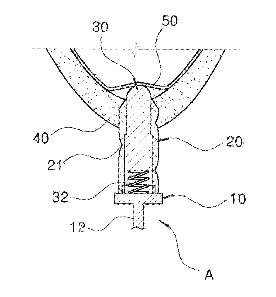
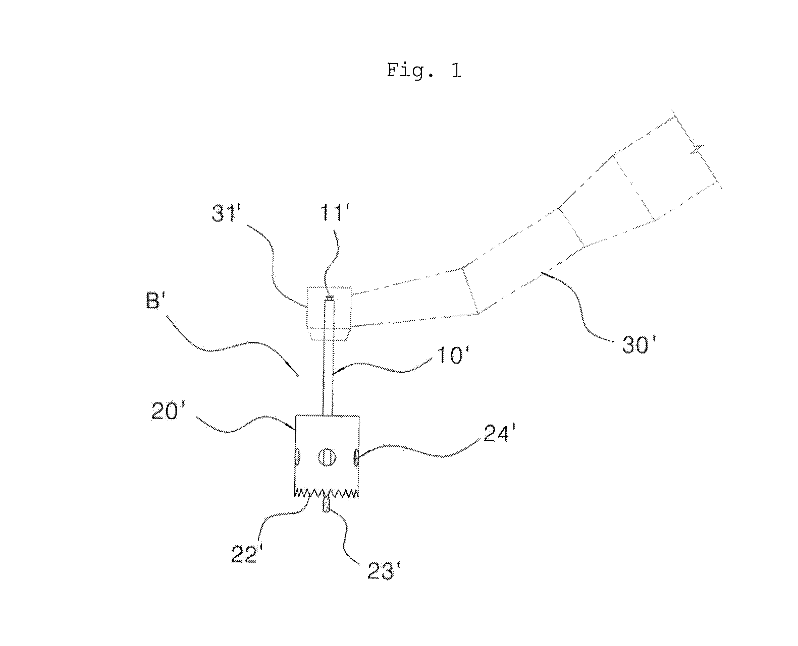
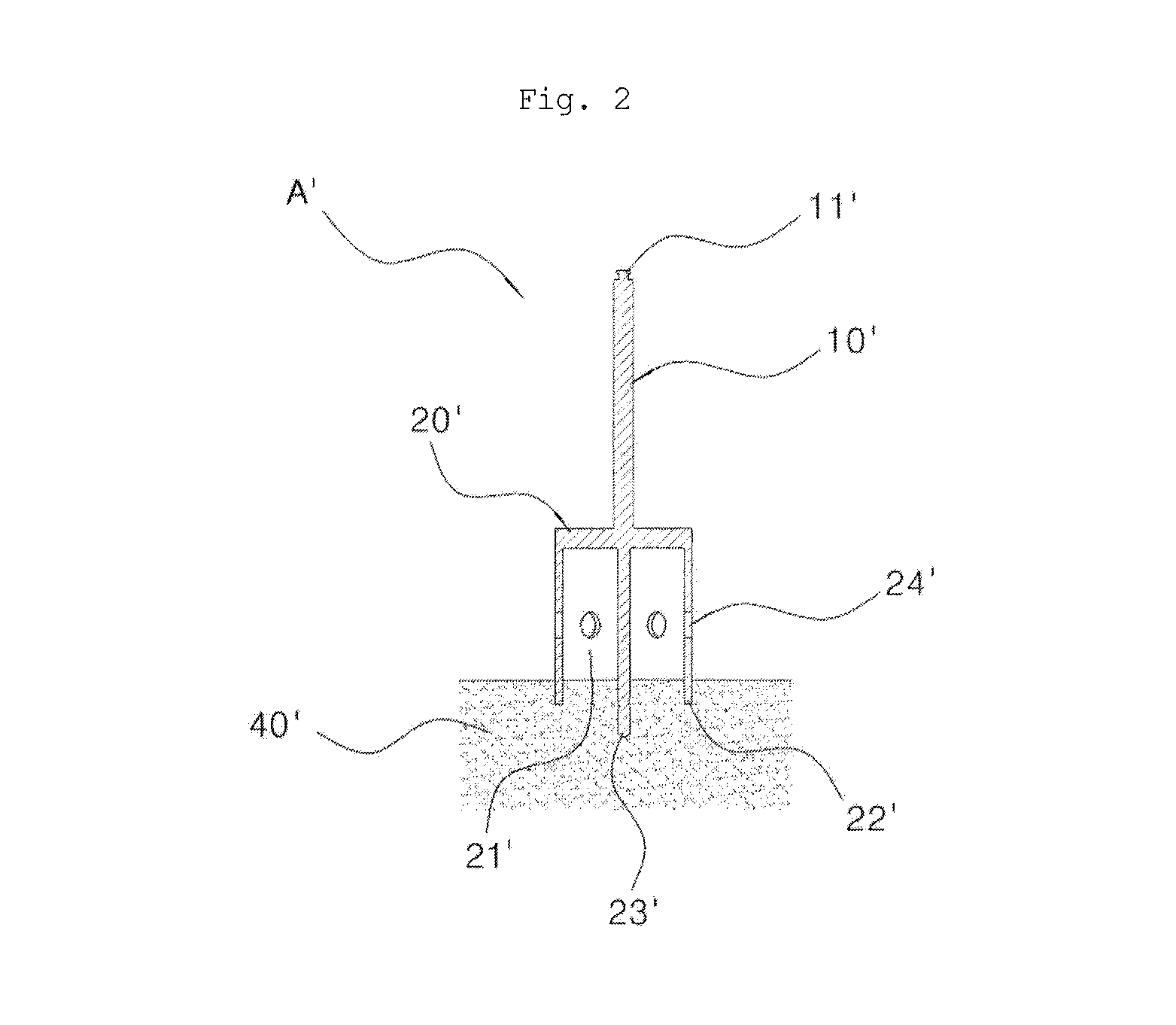
[0024]FIGS. 1 and 2 are views illustrating the operational states of a drill for forming a hole in the mucoperiosteum according to the present invention; FIG. 3 is a cross-sectional view illustrating the state in which a maxilla is drilled to form a hole by a twist drill according to the common present method; FIG. 4 is a cross-sectional view illustrating the state in which a maxillary sinus floor is penetrated using a sinus lift drill (SLD) according to the present invention; FIG. 5 is a cross-sectional view illustrating the state in which a maxillary sinus membrane is elevated by injecting graft into the same hole with hydraulic effect according to the present invention; FIG. 6 is a cross-sectional view illustrating the state in...


PUM


Abstract

The invention relates to a dental implant method using a tissue punch, sinus lift drill (SLD) and hydraulic effect which places a bone graft and embed a dental implant at a maxillary sinus area where there is not sufficient bone to embed a dental implant. The method includes: removing mucoperiosteum having a size of an dental implant to be implanted at a alveolar crest area using a tissue punch, drilling a maxillary sinus floor easily and safely without causing damage to a maxillary sinus membrane by inserting a sinus lift drill which has a protruding member that is elastically installed in the body so as to protrude from and retract in the longitudinal direction of the body, elevating a maxillary sinus membrane by the hydraulic effect (injecting graft adjacent to the drilled maxillary sinus floor); and installing the implant in an inside portion of the drilled maxillary sinus floor.

Description

BACKGROUND OF THE INVENTION[0001]1. Field of the Invention[0002]The present invention relates to a dental implant method, and more particularly, to a sinus bone graft method using a sinus lift drill (SLD) and hydraulic effect which can easily and simply drill a maxillary sinus floor without causing damage to a maxillary sinus membrane so that a dental implant can be installed in a short time.[0003]2. Description of the Related Art[0004]Recently, dental implant surgery for installing artificial teeth has been rapidly popularized in dental clinics.[0005]However, in case of some dental patients, the structure of the oral cavity makes it difficult to perform the implant surgery, so that the dental implant surgery becomes complicated, or some dentists often decline to give such a patient medical treatment.[0006]In particular, the dentist has difficulty in performing the implant installation in the case where a small amount of bone matrix remains in the posterior area near the maxillary s...

Claims


Application Information

Patent Timeline
Patent Type & Authority Patents(United States)
IPC IPC(8): A61B17/58A61B17/60A61F2/00
CPCA61C8/0006A61C8/0092
Inventor SONG, YOUNG-WAN
Owner SONG YOUNG WAN
Learn More