
Self-calibrating relaxation oscillator based clock source

a relaxation oscillator and self-calibration technology, applied in pulse generators, pulse automatic control, pulse techniques, etc., can solve the problems of large output frequency variation, long calibration time, and difficult to find space for an external crystal oscillator

Active Publication Date: 2011-12-27
SANDISK TECH LLC
View PDF20 Cites 20 Cited by
  • Summary
  • Abstract
  • Description
  • Claims
  • Application Information

AI Technical Summary

Benefits of technology

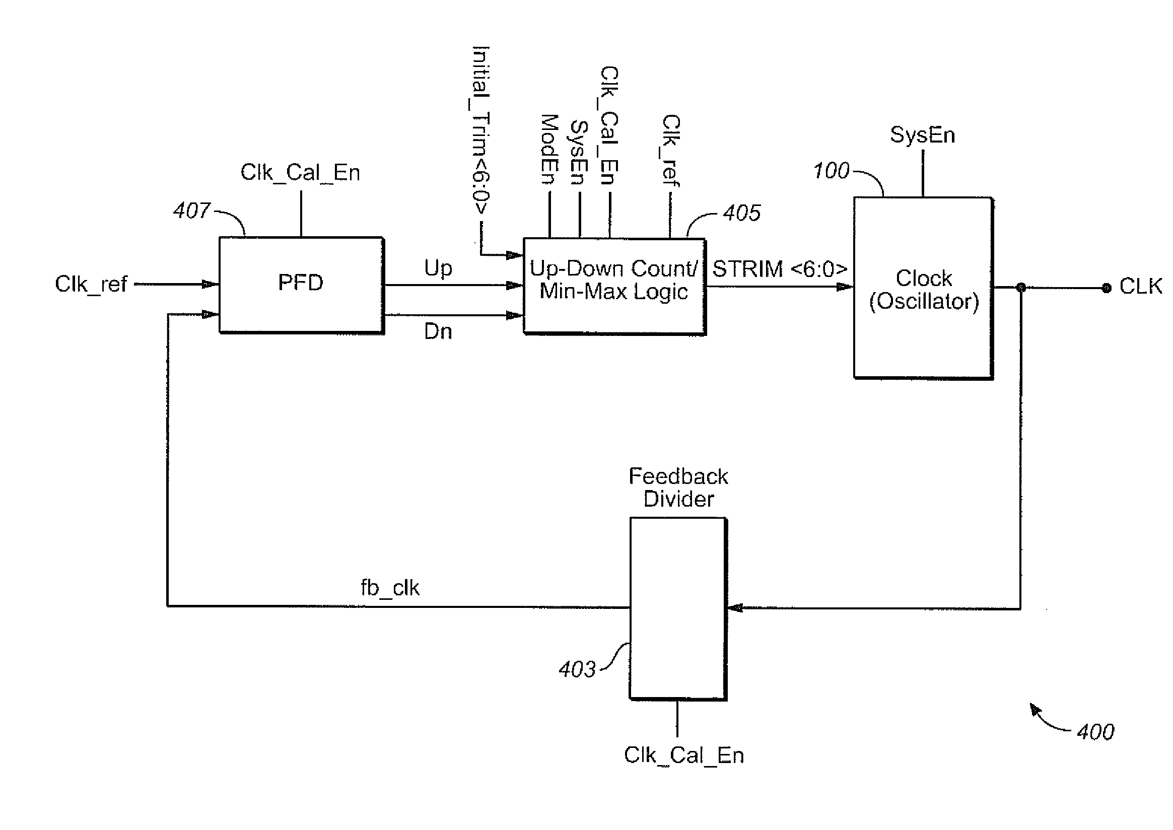
The invention is a circuit and method for calibrating the frequency of a clock circuit. It includes a relaxation oscillator that generates a calibratable output clock signal with a frequency dependent upon a trim value. The circuit also includes a frequency comparison circuit and a trim value adjustment circuit. The frequency comparison circuit compares the feedback clock signal with a reference clock signal and indicates whether the feedback clock signal has a higher or lower frequency. The trim value adjustment circuit uses an up-down counter and min-max logic to adjust the trim value in response to the indication. The method iteratively performs a process of generating a clock signal, comparing its frequency with a reference clock, and adjusting the trim value based on the comparison. The final trim value is determined based on the maximum and minimum of the trim value. The technical effect of the invention is to provide a reliable and efficient way to calibrate the frequency of a clock circuit.

Problems solved by technology

Although these PLL circuits are the standard way of providing an accurate clock signal, they have some drawbacks, particularly for applications, such as small form factor memory cards like the MicroSD cards, for example.
One of these drawbacks is that such devices have very small size boards, so that it becomes difficult to find space for an external crystal oscillator, which is needed as reference clock for PLLs.
The relaxation oscillator does not need external reference clock, but suffers from large output frequency variation mainly due to process dependence and so requires calibration.
This calibration time could be long due to manual intervention and needs costly equipment like high bandwidth oscilloscopes.

Method used


Image

  • Self-calibrating relaxation oscillator based clock source
  • Self-calibrating relaxation oscillator based clock source
  • Self-calibrating relaxation oscillator based clock source

Examples


Embodiment Construction

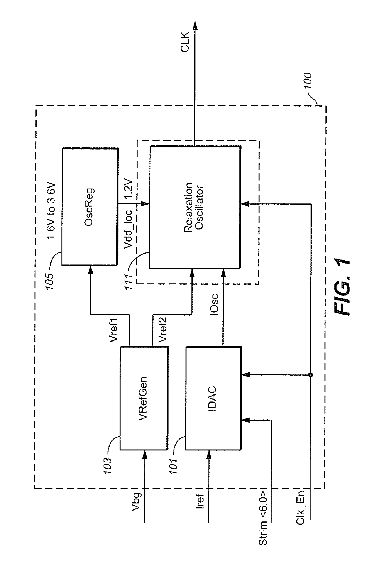
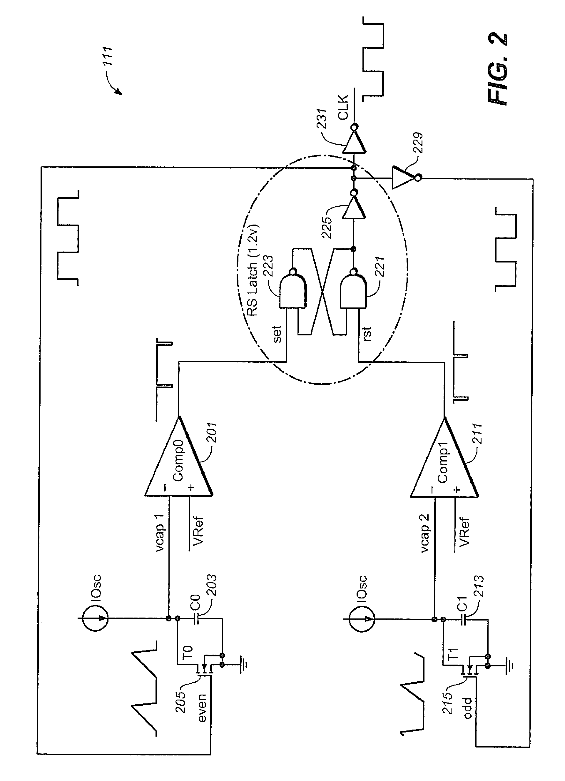
[0011]The following provides a technique and corresponding circuitry for a process independent, self-calibrating relaxation oscillator based clock source. Relative to the use of a phase locked loop (PLL), the use of a relaxation oscillator based clock source has the advantages of requiring little space and of lower cost. Although relaxation oscillators have been previously used for various applications, because of process variations they have tended to be relatively inaccurate and require a relatively long time to calibrate accurately. For example, under a typical prior art arrangement, the calibration time needed to accommodate the process variation of the relaxation oscillator can be on the order of a second or two and require costly external components, such as a high bandwidth oscilloscope, for calibration. The techniques and circuitry presented here can reduce the time needed for calibration significantly, to on the order of a few hundred micro seconds in the exemplary embodime...


PUM


Abstract

A technique and corresponding circuitry are presented for a process independent, self-calibrating relaxation based clock source. The technique and circuitry presented here can reduce the time and cost needed for calibration significantly. The relaxation based clock source produces a clock signal whose frequency is dependent upon a trim value. Starting from an initial trim value, the clock signal is generated, its frequency is compared with a reference clock frequency value, and the trim value is correspondingly adjusted up or down a bit at a time. After this process has continued for a while, min-max logic is used to determine the maximum and minimum trim values and, based on these, the final trim value for the clock is set. This calibration process can also be used to extract whether, and by how much, the implementation on silicon of a particular chip lies in the fast or slow process corners.

Description

FIELD OF THE INVENTION[0001]This invention pertains generally to the field of clock sources for integrated circuits and, more particularly, to relaxation oscillator based clock sources and their calibration.BACKGROUND[0002]System on Chip (SoC) Circuits often have embedded clock sources, frequently a phases locked loop (PLL) that generates the clock signal. Although these PLL circuits are the standard way of providing an accurate clock signal, they have some drawbacks, particularly for applications, such as small form factor memory cards like the MicroSD cards, for example. One of these drawbacks is that such devices have very small size boards, so that it becomes difficult to find space for an external crystal oscillator, which is needed as reference clock for PLLs. Another is that if the use of a crystal could be eliminated, the cost saving can be significant for a high volume product. The relaxation oscillator is widely used clock source as an alternative to PLLs. The relaxation o...

Claims


Application Information

Patent Timeline
Patent Type & Authority Patents(United States)
IPC IPC(8): H03L7/085H03K3/02
CPCH03K4/502H03L7/099H03L7/089H03K3/0231H03K3/011H03K3/023
Inventor PANCHOLI, DEEPAKODEDARA, BHAVINPRASAD, NAIDUBOJJA, SRIKANTHSABBINENI, SRINIVASA RAONARADASI, JAYAPRAKASH
Owner SANDISK TECH LLC
Learn More