Method and system for generation of a user interface

a user interface and user interface technology, applied in the field of data processing and medical technology, can solve the problems of laborious operation and the inability to adapt the user interface to the respective application, and achieve the effect of optimizing with regard to the space requirement on the screen

Inactive Publication Date: 2011-12-27
SIEMENS AG
View PDF12 Cites 2 Cited by
  • Summary
  • Abstract
  • Description
  • Claims
  • Application Information

AI Technical Summary

Benefits of technology

[0008]An object of the present invention is to provide a way to improve a user interface for controlling applications for a complex medical technology apparatus in particular for a magnetic resonance tomography apparatus, in particular to dynamically and flexibly focus on the respective application and to optimize with regard to the space requirement on the screen.
[0014]In order to enable easier handling for the user, individual control elements can be combined into control groups. These are then presented on the user interface in a structured or consolidated manner. For example, if the control elements are parameter input possibilities or other textual control elements, a control group can be a group of a number of control elements that is displayed as a folder or index card on the user interface. The structuring of the control elements can ensue according to pre-configurable structuring criteria. The control elements that exhibit a connection in terms of content are normally combined in one card. Moreover, it is possible to also recognize temporal correlations and to group together such control elements that must be activated by the user in successive steps. This leads to an easier and more efficient handling of the application.
[0020]In a further embodiment of the invention a reference is associated with a user interface generated for at least one application, by means of which reference the user interface can be retrieved and / or can be executed at a later point in time, in particular upon execution of the application. The association normally ensues via a name and is unambiguous. In other words, a generated user interface can be unambiguously selected or, respectively, determined via a name associated with it. This procedure is also designated as an ASSIGN procedure. All generated user interfaces and the respective names associated with them are typically stored in a corresponding data structure. The user thus can obtain an overview of which user interfaces can be selected in principle. Moreover, it is possible that a specific generated user interface is selected for an application is selected from a set of user interfaces. Here the user can also select from pre-configurable names. As soon as the user has selected a user interface for use, this is activated and presented on the screen. This procedure is also designated as a USE procedure. A high flexibility can be achieved with this solution, by allowing a number of user interfaces that are optimally designed for the respective usage or application to be selected and by allowing the point in time for activation of a user interface to be arbitrarily determined by the user.
[0022]In another embodiment of the invention, the method starts with an existing user interface and alters (in particular expands or limits) the presented control elements and / or the presented control groups thereof. Upon generation of a new user interface, the user does not have to unnecessarily reconfigure already-existing control elements again, but rather can already start from predefined elements. This produces a significant time gain in the generation of user interfaces. Moreover, a safety aspect is also achieved because the user is made aware of necessary control elements for the respective application, and thus these elements cannot be accidentally omitted in the generation of the user interface for that application.
[0024]An important aspect of the inventive solution is that a change between different user interfaces for the same application is also possible at the time of execution. Scenarios thus can be covered that, for example, concern a user change or another change in the context of the application execution. The application does not have be restarted again, which increases the performance of the system overall.
[0030]Thus a customized user interface can be achieved in accordance with the invention for each application case, the operation of this customized user interface being significantly more ergonomic, faster and simpler since only the respective relevant parameters (for example measurement and / or post-processing parameters) are displayed. Since the layout is optimized with regard to the relevant parameters and, usually, the parameters frequently match a single parameter card, no card changes are necessary. The handling is thus easier for the user and the orientation time for inexperienced users can be reduced, since they are only confronted with the relevant parameters. Overall the screen space for the presentation of the control elements can be minimized.

Problems solved by technology

Surveying the displayed parameters is therefore a very time-intensive and error-prone process and overall results in a very laborious operation.
In conventional systems it has not been possible to adapt the user interface to the respective application and to display, in an ergonomically reasonable arrangement, only the parameters that are relevant for the respective application.

Method used


Image

  • Method and system for generation of a user interface
  • Method and system for generation of a user interface
  • Method and system for generation of a user interface

Examples


Embodiment Construction

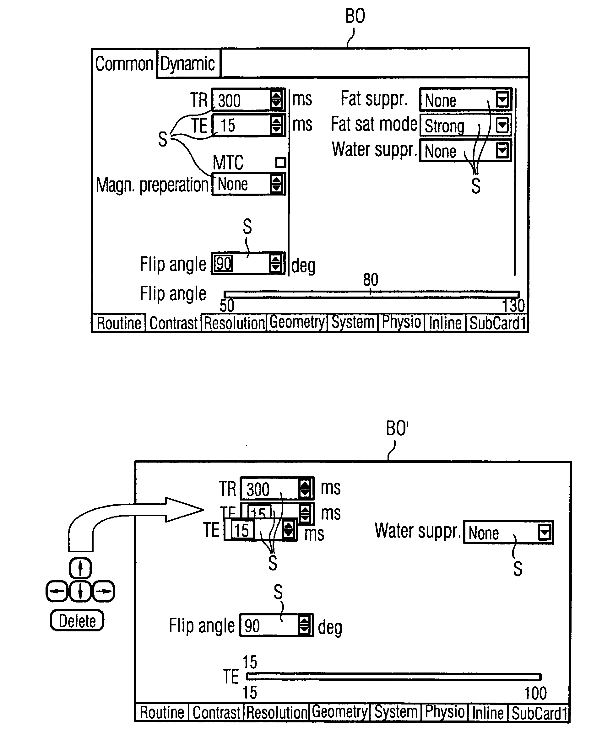
[0039]The inventive method seeks to generate a user interface BO automatically, dependent on the respective application to be implemented via the user interface BO.

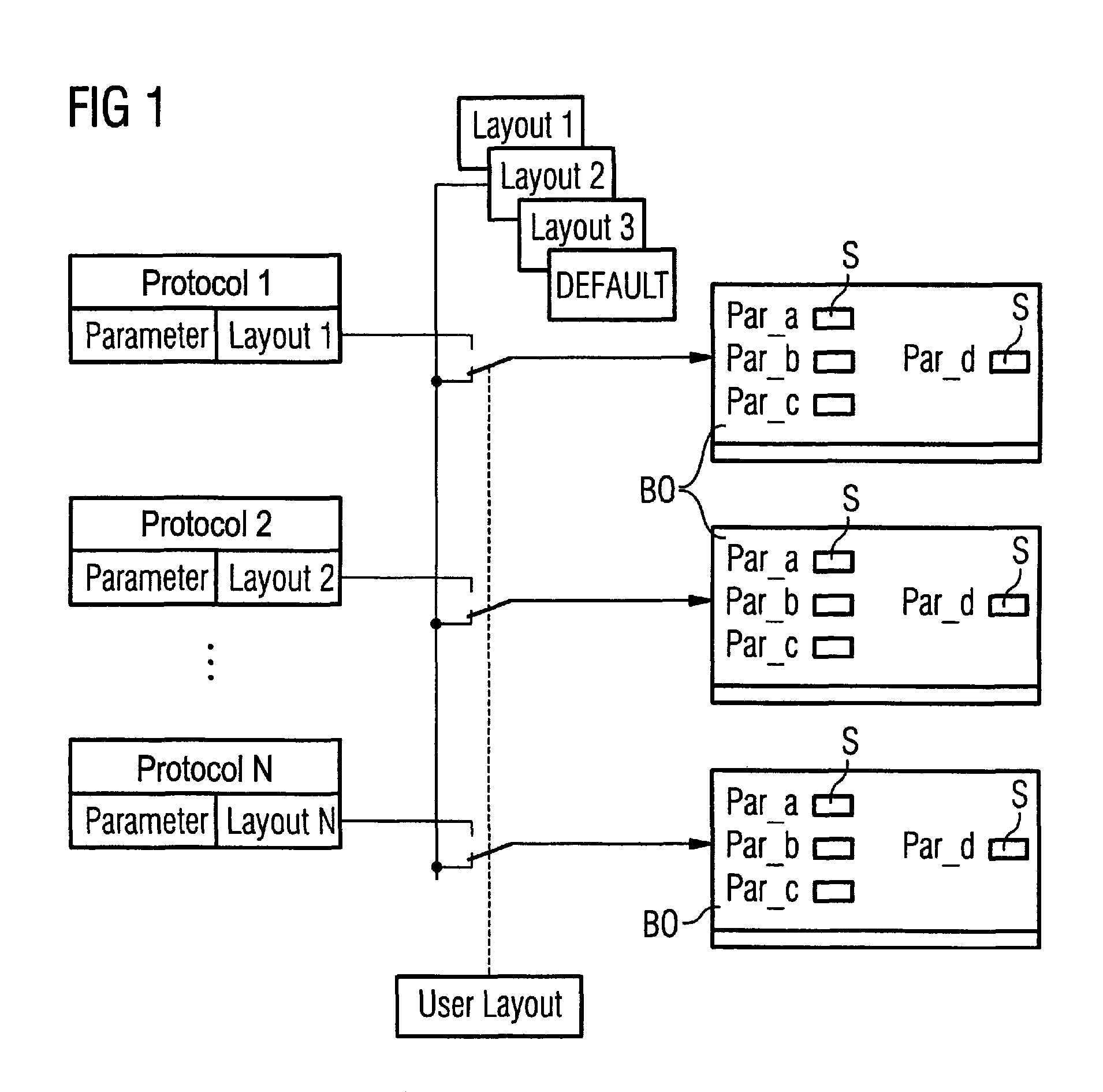
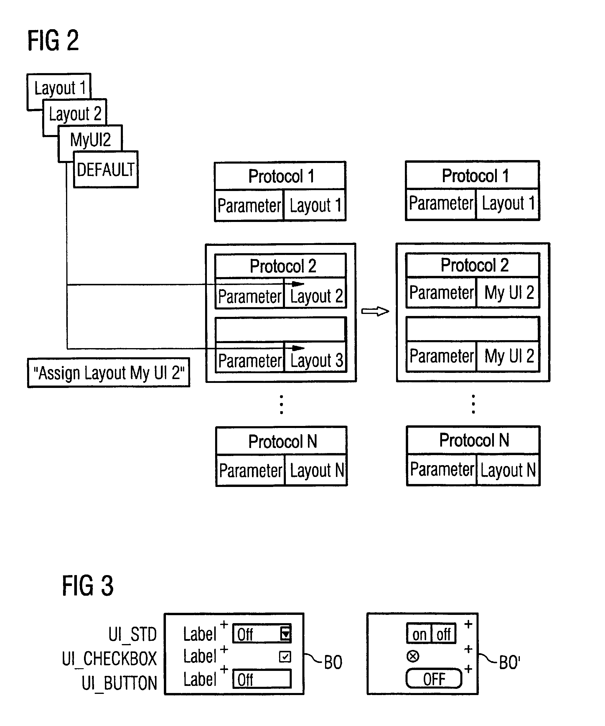
[0040]For this purpose, in a first step the application is determined for which the user interface BO should be generated. Items known as control elements S are subsequently registered, preferably automatically. The control elements S are essentially parameter input options that are presented as elements on the user interface BO. As is apparent from the figures, these can either be fields for a textual or numerical input, selection possibilities from a menu representation, or other control elements that can be activated by a user input, for example by a keyboard, mouse or other computer input components. In an embodiment of the invention, the respective control elements S are to be structured, grouped or consolidated into control groups. A control group is typically what is known as a parameter card (also called a folder)...


PUM


Abstract

In a method and system for generating a user interface for at least one medical application to be implemented by a medical apparatus, a designation of the medical application to be implemented is provided to a computerized processor, which automatically then registers only control elements for inclusion in the user interface that are relevant for controlling the designated medical application. The processor automatically positions control elements, individually or in groups, in the user interface at a display screen according to configurable positioning criteria that minimize at least one of space on the display screen occupied by the control elements, and user steps to activate the control elements, to form the user interface.

Description

BACKGROUND OF THE INVENTION[0001]1. Field of the Invention[0002]The present invention concerns data processing and medical technology and in particular concerns a method, a system, and a storage medium encoded with a computer program for designing user interfaces for complex medical technology apparatuses such as, for example, magnetic resonance tomography systems.[0003]2. Description of the Prior Art[0004]A number of settings and configurations that require different user interfaces dependent on the respective application are necessary to control a complex system such as a magnetic resonance tomography system. If one envisions the number of possible applications for a magnetic resonance apparatus (for example sequence techniques, post-processing applications, etc.) that each require different user inputs as control elements for the application (such as, for example, time specifications, details for the post-processing steps, upper limits and lower limits, etc.), it is clear that ma...

Claims


Application Information

Patent Timeline
Patent Type & Authority Patents(United States)
IPC IPC(8): G06F3/14
CPCA61B5/055A61B5/7435A61B5/7475G06F8/38G01R33/546
Inventor LIST, STEFFEN
Owner SIEMENS AG
Why Eureka
Try Eureka