Orthopedic retaining system

a technology of retaining system and orthopedic artery, which is applied in the field of orthopedic artery retaining system, can solve the problems of both possible movement blockages

Active Publication Date: 2012-01-03
AESCULAP AG
View PDF40 Cites 72 Cited by
  • Summary
  • Abstract
  • Description
  • Claims
  • Application Information

AI Technical Summary

Benefits of technology

[0008]The advantage of this configuration is that the step-wise blocking of the free movability is brought about by one and the same clamping device and so the operator can block the individual movements one after the other with only one tool for actuating the clamping device. By using an elastic pressure element, the operator has, in addition, the possibility of selecting the clamping forces such that when the elastic pressure element abuts on the clamping element the pivotability of the threaded shaft in relation to the head part is restricted but not completely terminated. This enables the operator to pivot the threaded shaft in relation to the head part by using a specific force; the position, once set, is, however, essentially maintained unless the operator readjusts it by applying this force. As a result, the adjustment of the retaining system is simplified since, in this phase, the free pivotability is restricted whereas the free displaceability of the retaining bar is still possible.
[0010]In a preferred embodiment, it is, however, provided for the retaining bar to rest on the clamping element. As a result of this, the elastically deformable pressure element presses the retaining bar against the clamping element when it is displaced into the clamping position and, as a result, presses the clamping element against the threaded shaft, i.e., when the clamping device is actuated completely, the elastic pressure element is not only supported on the clamping element but also exerts additional clamping forces on the clamping element via the retaining bar so that, as a result, a particularly secure fixing in position against all types of movement is possible.
[0014]In a further, preferred embodiment, it is provided for the elastic pressure element to be a disc which is arranged in the interior space of the head part, can be elastically deformed and the edge of which is supported on the clamping element. This configuration has the advantage that it is rotationally symmetric and can be used independently of any installation direction of the elastic pressure element.
[0019]It is favorable when the elastic pressure element and the actuating element are rotatable relative to one another about an axis extending concentrically to the longitudinal axis of the head part. In this way, the actuating element, for example, a clamping screw can be turned about this axis without the elastic pressure element being turned; it can rest on the clamping element in a non-rotatable manner.

Problems solved by technology

This can be disadvantageous since, for the purpose of aligning the orthopedic retaining system in these arrangements, either the retaining bar is freely displaceable and also the threaded shaft pivotable or, however, both possibilities for movement are blocked.

Method used


Image

  • Orthopedic retaining system
  • Orthopedic retaining system
  • Orthopedic retaining system

Examples


Embodiment Construction

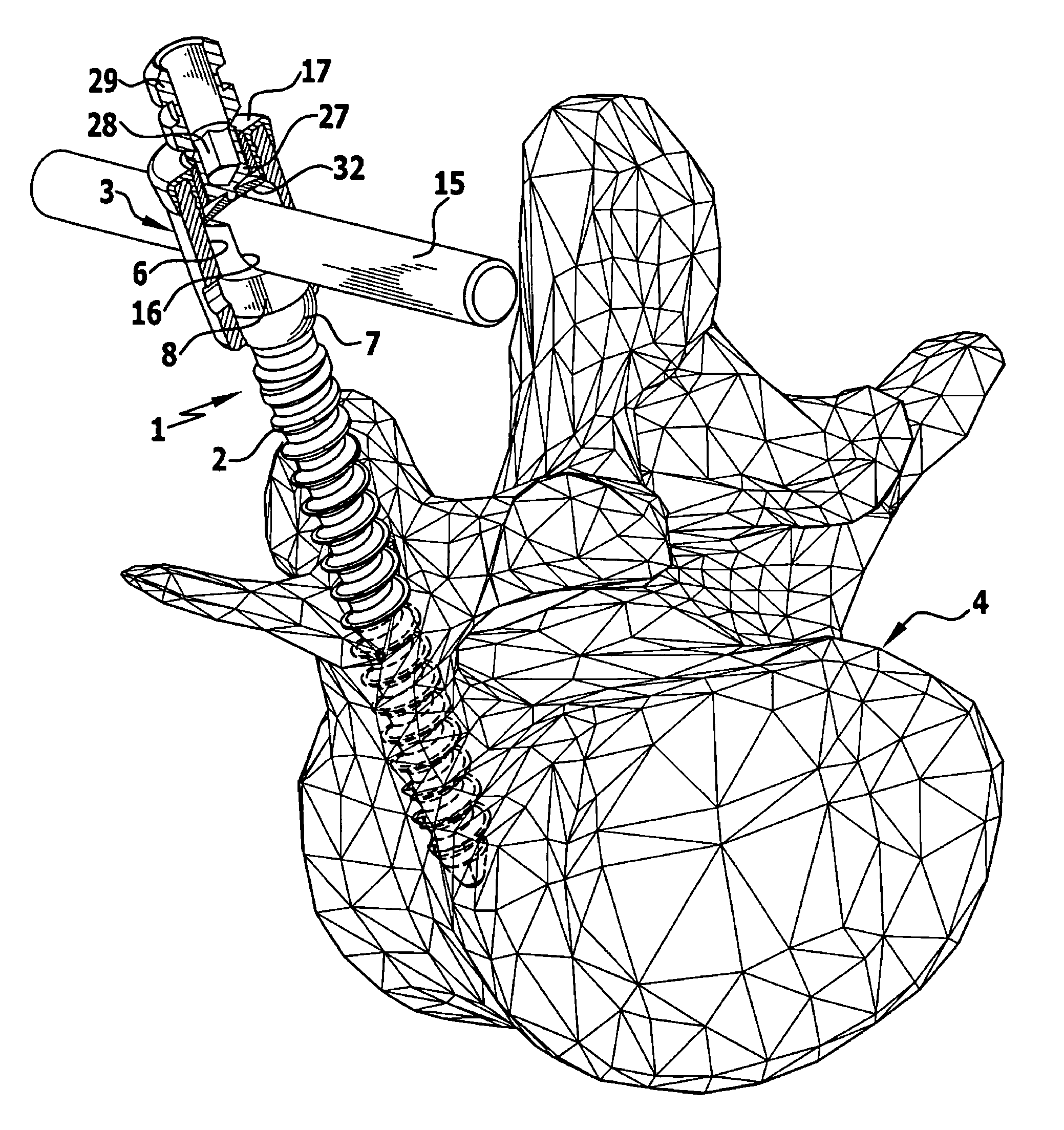
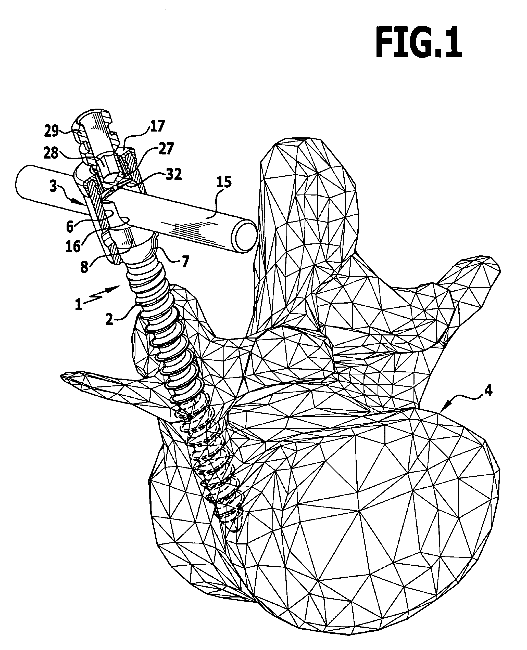
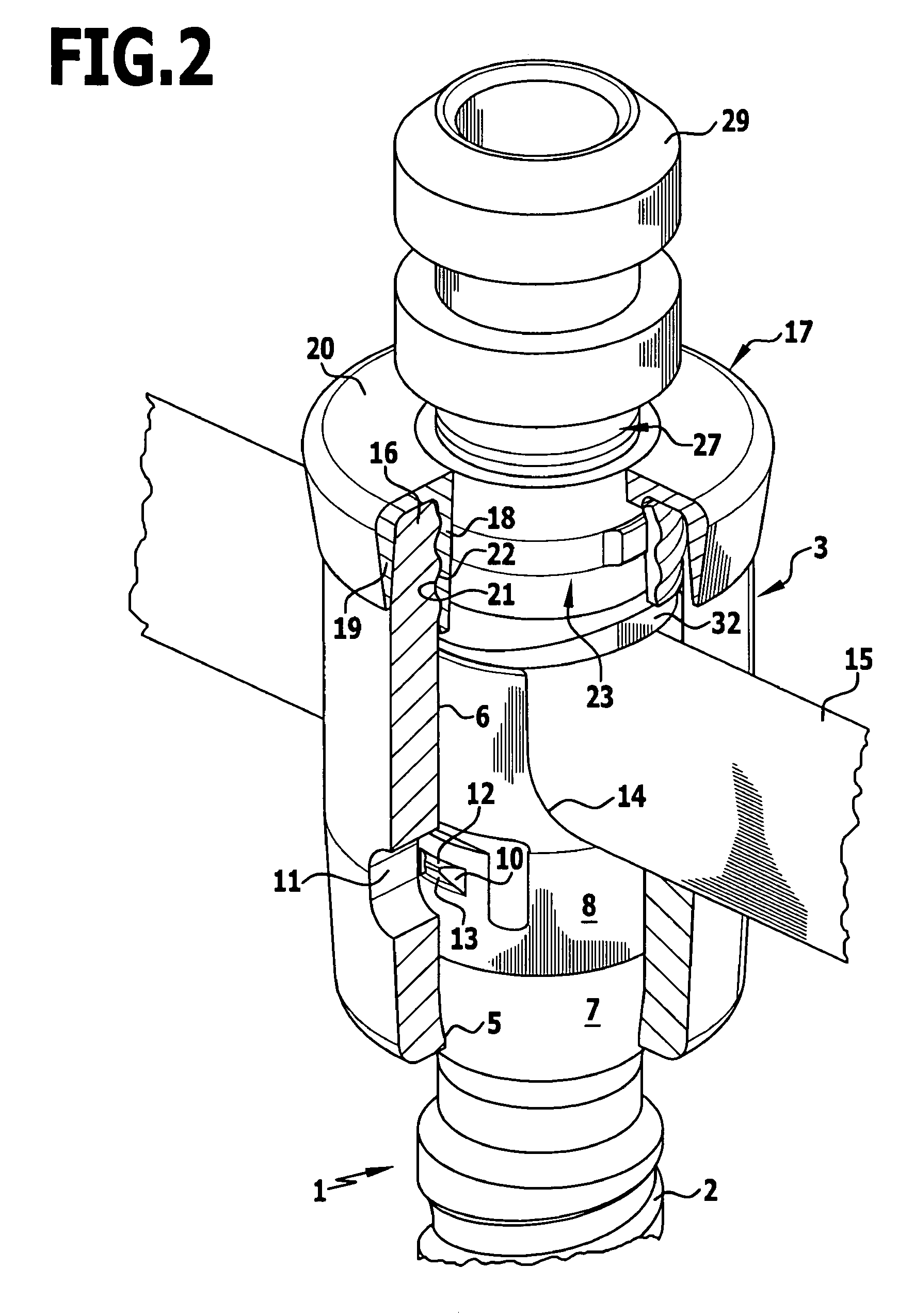
[0026]The orthopedic retaining system illustrated in the drawings comprises a bone screw 1 with a threaded shaft 2 and a head part 3. The threaded shaft 2 is provided with a bone thread which is preferably self-cutting and can be screwed into a bone, in the embodiment illustrated in FIG. 1 into a vertebral bone 4. The threaded shaft 2 is connected to the head part 3 in the embodiment illustrated so as to be pivotable to all sides. For this purpose, the head part 3, which essentially has the shape of a cylinder sleeve, has a cylindrical interior space 6 which narrows at the lower end in the form of a constriction 5 and into which the threaded shaft 2 can be introduced from above. The threaded shaft 2 has at its upper end a spherical thickened area 7, the outer diameter of which corresponds to the inner diameter of the interior space 6 and which is supported at the lower end on the constriction 5 of the interior space 6 so that a ball-joint connection is formed between the threaded sh...


PUM


Abstract

An orthopedic retaining system comprising at least one bone screw which has a head part and a threaded shaft pivotally mounted thereon is disclosed. A clamping element is mounted in the head part, which can be pressed against the threaded shaft from its upper side and, as a result, secure the threaded shaft relative to the head part. A retaining bar is arranged in a receptacle of the head part and extends essentially transversely to the threaded shaft. A clamping device is provided on the upper side of the head part, by means of which the clamping element and the retaining bar are pressed into the head part such that the threaded shaft and the retaining bar are secured in position relative to the head part. The clamping device comprises an elastically deformable pressure element which is displaced into a clamping position during actuation of the clamping device.

Description

[0001]This application claims the benefit of German patent application no. 10 2007 042 953.5 filed Aug. 30, 2007, which is incorporated herein and made a part hereof by reference.BACKGROUND OF THE INVENTION[0002]The invention relates to an orthopedic retaining system comprising at least one bone screw which has a head part and a threaded shaft pivotally mounted on it, a clamping element which is mounted in the head part, can be pressed against the threaded shaft from the upper side of the head part and, as a result, secures the threaded shaft relative to the head part, a retaining bar which is arranged in a receptacle of the head part and extends essentially transversely to the threaded shaft and a clamping device on the upper side of the head part, by means of which the clamping element and the retaining bar are pressed into the head part in such a manner that the threaded shaft and the retaining bar are secured in position relative to the head part.[0003]Orthopedic retaining syste...

Claims


Application Information

Patent Timeline
Patent Type & Authority Patents(United States)
IPC IPC(8): A61B17/04
CPCA61B17/7037A61B17/7032
Inventor SCHUMACHER, JOERG
Owner AESCULAP AG
Why Eureka
Try Eureka