

Exhaust heat recovery for engine heating and exhaust cooling
a technology of exhaust heat recovery and engine heating, applied in the field of heat exchange, can solve the problems of viscous energy loss, higher emissions, energy loss, etc., and achieve the effects of reducing energy loss, reducing heat loss in the combustion chamber, and reducing engine pumping loss
- Summary
- Abstract
- Description
- Claims
- Application Information
AI Technical Summary
Benefits of technology
Problems solved by technology
Method used
Image

Examples
Embodiment Construction
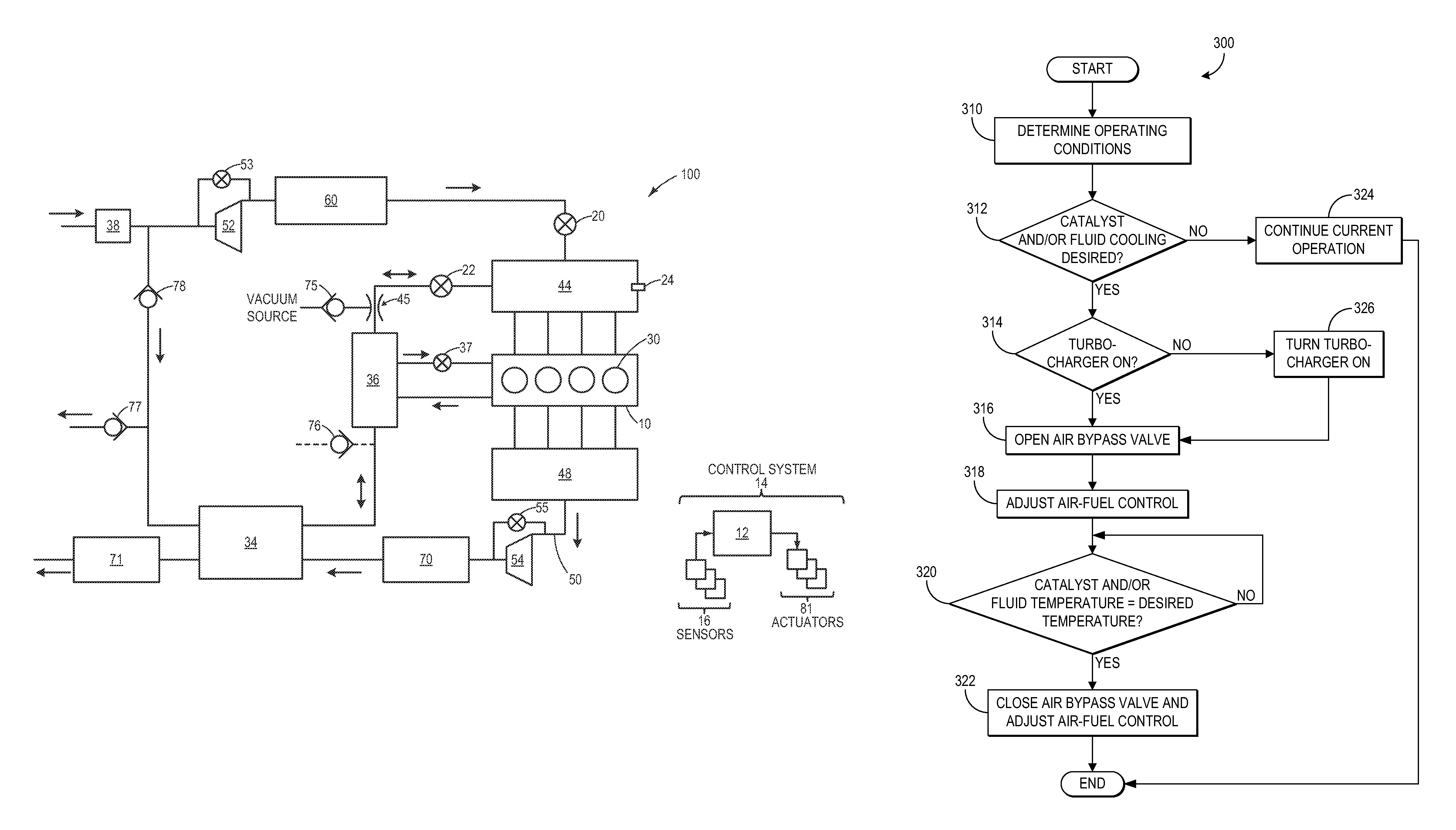
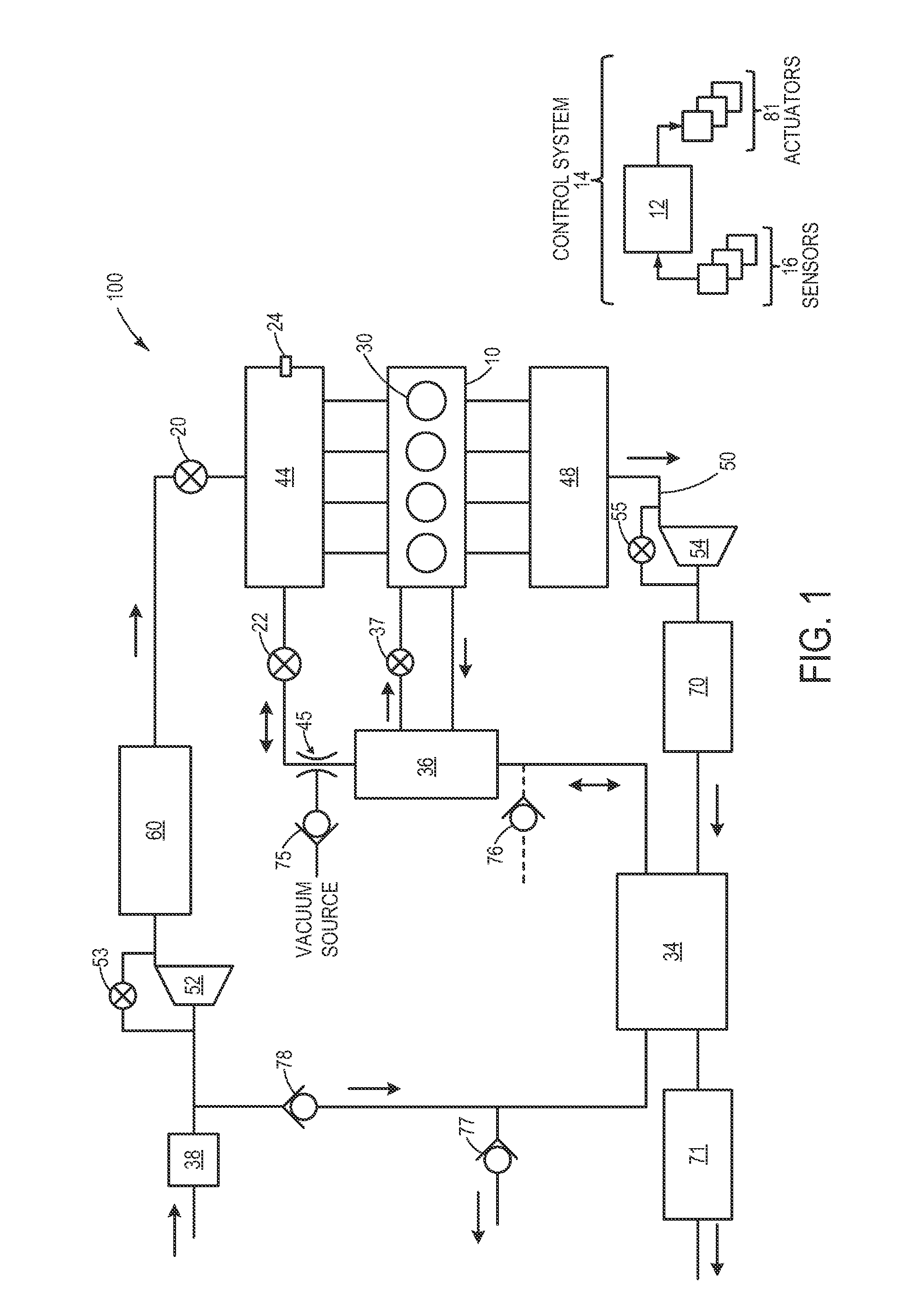
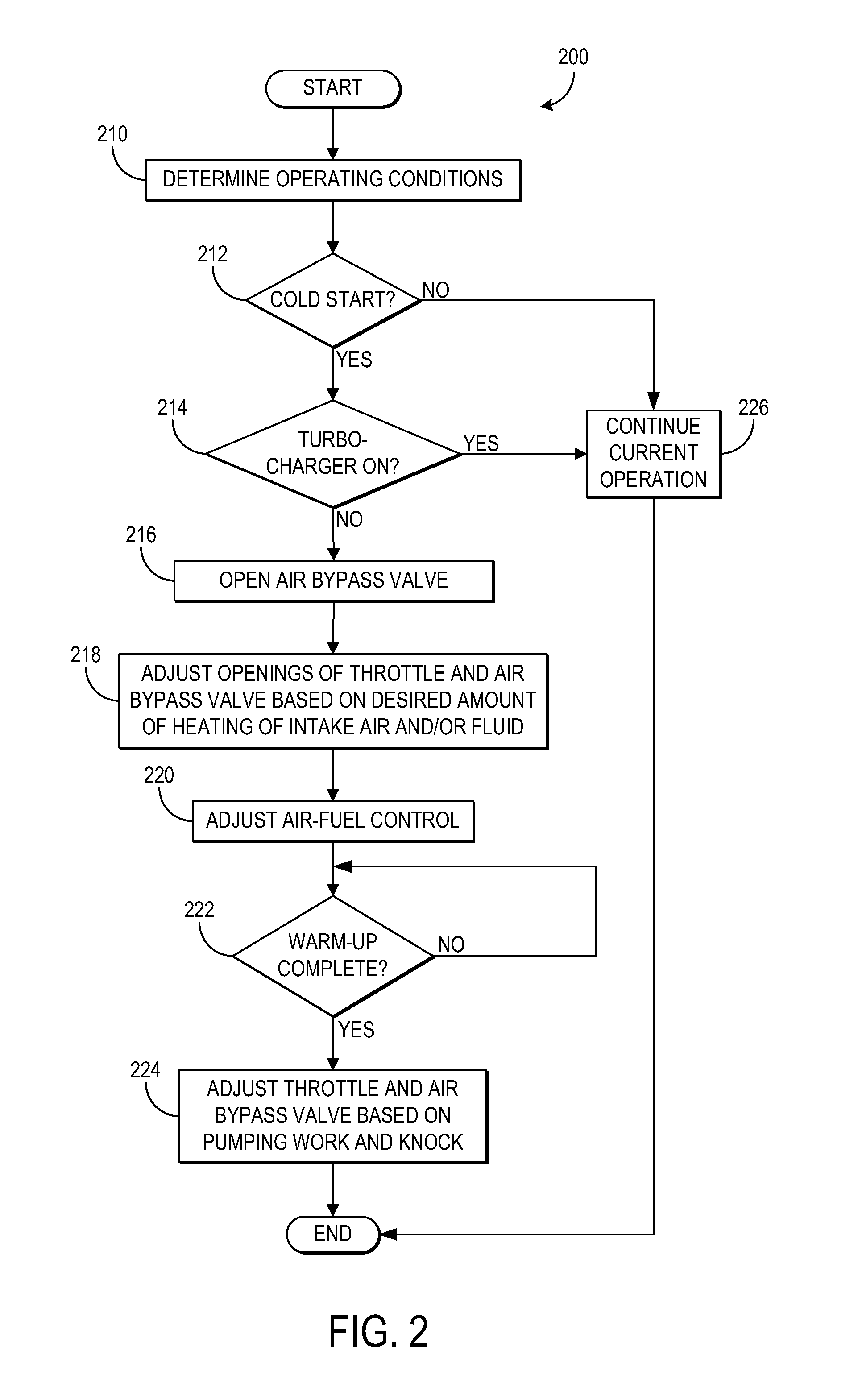
[0011]The following description relates to systems and methods for heating an engine in a vehicle during a cold start. In one example, intake air flowing in a first direction may be heated through a heat exchange with exhaust gas via a gas-to-gas heat exchanger. The heated intake air may subsequently undergo a second heat exchange with a powertrain fluid (e.g., engine oil, transmission fluid, etc.) via a gas-to-liquid heat exchanger such that the powertrain fluid is heated. As such, viscous energy losses due to relatively cold fluid may be reduced, and combustion chamber heat loss and pumping losses are also reduced due to the heated intake air. Furthermore, in another example, when pumping loss reduction and powertrain fluid heating are not desired, but exhaust cooling is desired, intake air may flow through the heat exchangers in a second direction such that the exhaust is cooled for exhaust catalyst cooling, for example.
[0012]FIG. 1 shows a schematic diagram of vehicle system 100...
PUM
 Abstract
Description
Claims
Application Information