Hydraulic valve circuit with damage-control override

a technology of hydraulic valve and override, which is applied in the direction of mechanical equipment, servomotors, transportation and packaging, etc., can solve the problems of load dislodging from the clamping member, operator using too little clamping force, and load damage in various ways

Active Publication Date: 2012-01-10
CASCADE CORP
View PDF17 Cites 11 Cited by
  • Summary
  • Abstract
  • Description
  • Claims
  • Application Information

AI Technical Summary

Problems solved by technology

Damage to the load may occur in various ways.
The operator may use too little clamping force when attempting to grasp and then lift the clamped load.
As a result the load may become dislodged from the clamping members and sustain impact damage.
The result of using too much clamping force may be a crushed or deformed load.
Damage to the load or to adjacent structures such as surrounding walls or trailers, railcars, containers or warehouses, may also occur if excessive pinwheeling or backhanding force is applied.
For example, using too much force to reposition a load against a trailer wall might result in crushing or deforming the load as it is compressed between the outward surface of one of the clamp members and the trailer wall, or deforming or even breaking the trailer wall itself.

Method used


Image

  • Hydraulic valve circuit with damage-control override
  • Hydraulic valve circuit with damage-control override
  • Hydraulic valve circuit with damage-control override

Examples


Embodiment Construction

[0012]In the following detailed description, numerous specific details are set forth in order to provide a thorough understanding of the preferred embodiments. However, those skilled in the art will understand that the present invention may be practiced without these specific details, that the present invention is not limited to the depicted embodiments, and that the present invention may be practiced in a variety of alternate embodiments. In other instances, well known methods, procedures, components, and systems have not been described in detail.

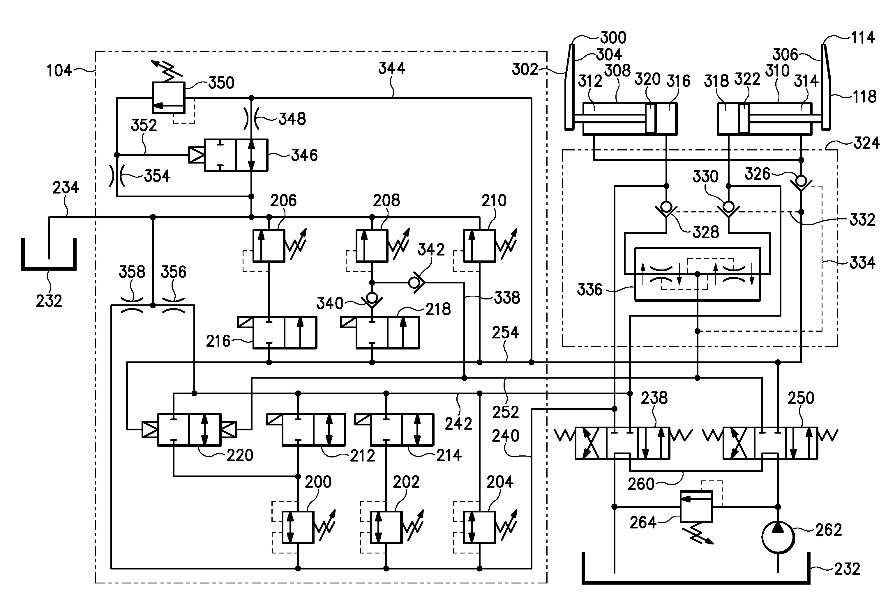
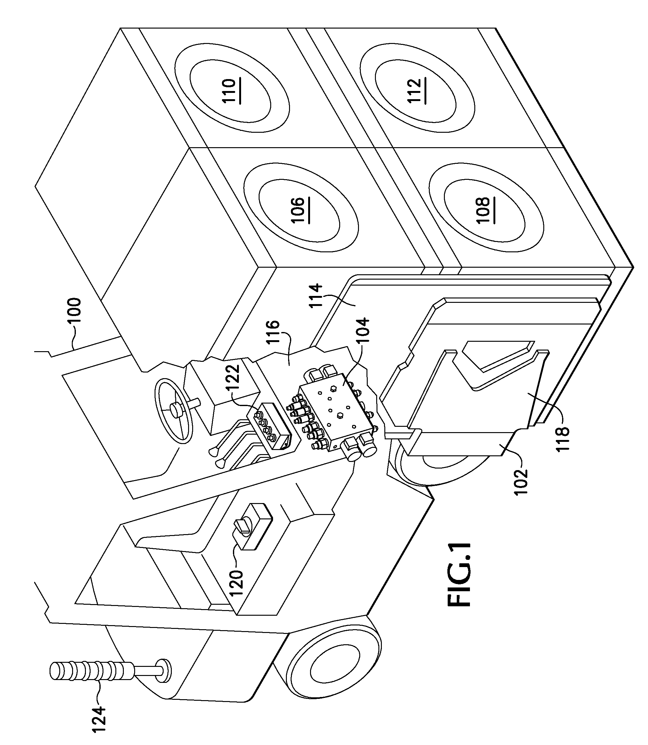
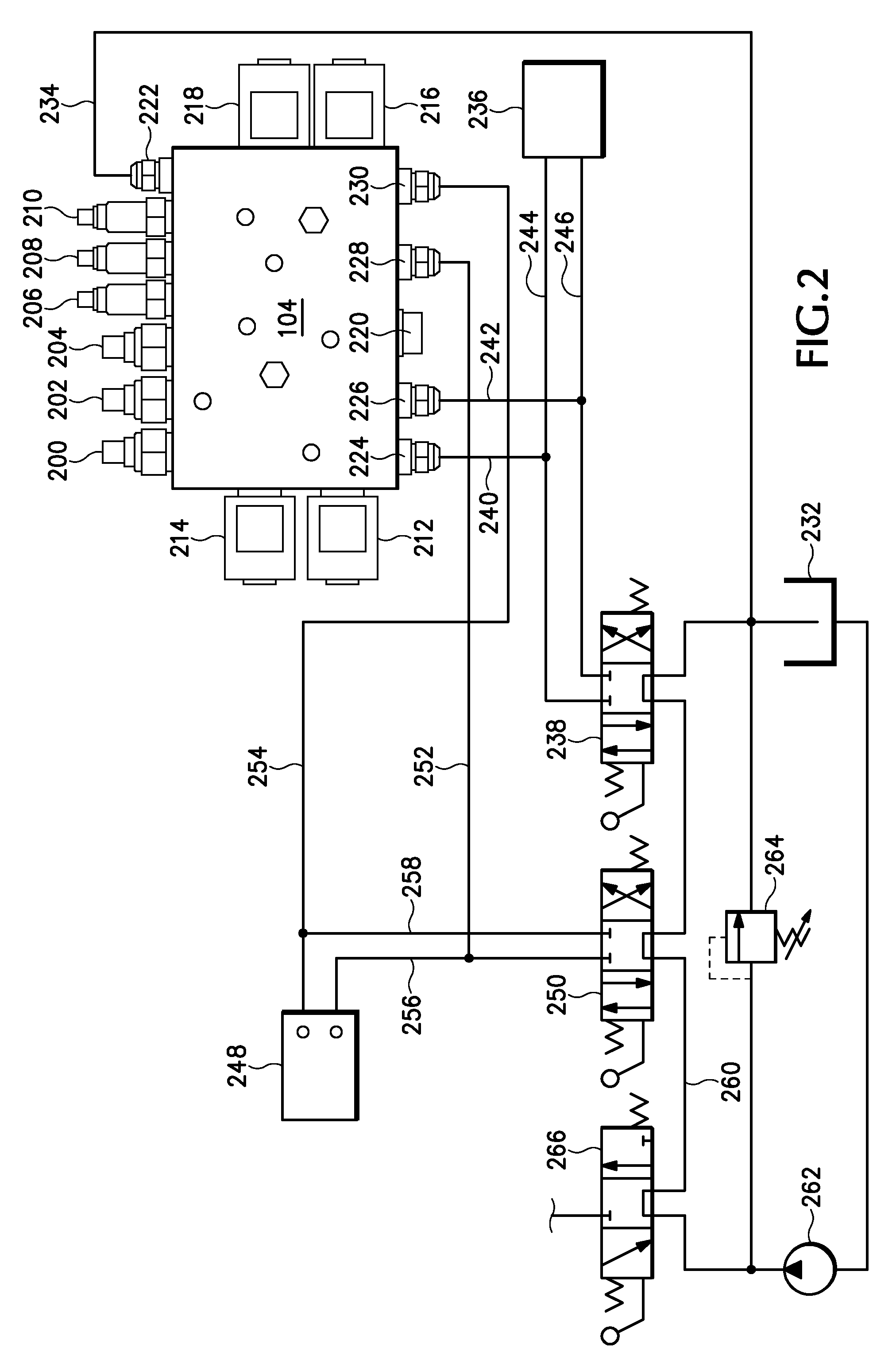
[0013]As an overview, the preferred embodiments generally involve hydraulic valve circuits adapted to control load-handling members, such as forks or clamp arms, associated with material handling equipment. Preferably, the hydraulic valve circuits may be used for any type of hydraulic device having sliding or pivoting load-handling members and having variably selectable maximum forces with which the load-handling members move toward and aw...


PUM


Abstract

Hydraulic valve circuits capable of variably limiting respective maximum hydraulic pressures at which an assembly of bidirectional hydraulic power devices can move respective clamping members, such as forks or clamp arms, selectively in a closing movement toward each other, in an opening movement away from each other, or in a side-shifting movement in unison with each other, so as to provide damage-control capabilities for the control of the clamping members. The circuits preferably include one or more pressure-regulating valves interconnected with the assembly of power devices, and capable of variably limiting a maximum side-shifting pressure, at which said assembly can cause said side-shifting movement, in response to a maximum pressure selection. The circuits preferably include at least one override assembly, capable of overriding the maximum pressure selection to thereby lower the maximum side-shifting pressure automatically irrespective of the maximum pressure selection.

Description

BACKGROUND OF THE INVENTION[0001]This disclosure relates generally to hydraulic valve circuits for use with material handling equipment and, more particularly, to hydraulic valve circuits adapted to control transversely movable members such as forks or clamp arms associated with material handling equipment, and to provide damage-control override capabilities for the control thereof.[0002]Material handling equipment used for moving palletized or non-palletized loads from place to place, such as, for example, in a warehouse, typically includes forklift trucks or other types of vehicles equipped with material handling attachments having load-lifting members such as forks or clamp arms. For example, on a typical forklift truck, load-lifting forks are attached to a carriage which is in turn movably attached to a mast so as to travel vertically for raising and lowering the forks. Various different types of attachments may also be mounted on the carriage. For example, a fork side-shifter w...

Claims


Application Information

Patent Timeline
Patent Type & Authority Patents(United States)
IPC IPC(8): F15B11/20
CPCB66F9/22B66F9/183
Inventor PETRONEK, DAVID W.
Owner CASCADE CORP
Why Eureka
Try Eureka