Fluted hopper tee

a hopper hopper and hopper technology, applied in the field of hopper tees, can solve problems such as affecting the performance of hoppers, and achieve the effect of reducing the number of hoppers

Active Publication Date: 2012-01-10
BULK TANK
View PDF12 Cites 10 Cited by
  • Summary
  • Abstract
  • Description
  • Claims
  • Application Information

AI Technical Summary

Benefits of technology

[0015]This invention provides a directional hopper tee with an internally fluted vertical pipe blending into a horizontal pipe. The hopper tee has a vertical pipe with an opening that connects to a hopper, or bin, to receive bulk material into the tee and a horizontal pipe centered upon one end of the vertical pipe. The horizontal pipe has an inlet that receives bulk material and pressurized air from ahead of the hopper and an opposite outlet that discharges the bulk material already flowing in the horizontal pipe and that received from the hopper through the vertical pipe. The vertical pipe has a flange that abuts the hopper and an opening in the flange that matches the opening of a valve on the hopper itself. At the opening, the vertical pipe begins to turn towards the outlet of the lower pipe with a flute. The flute begins immediately at the flange resulting in a vertical pipe with a curved shape towards the outlet and a square shape towards the inlet. The present invention raises the ground clearance of the horizontal pipe by at least one inch resulting in a hopper tee that clears at least 7 inches above the ground. The hopper tee of the invention also unloads up to and including 22% more product per minute than prior art tees during field conditions. Alternate embodiments of the present invention provide a reinforced flange, a drop tee, and a low profile drop tee. The present invention aids in the unloading of bulk materials from various truck, rail, and ship transporters.
[0016]During unloading of bulk materials through the invention, the materials contact the tee and its various parts. Such contact induces friction between the materials and the tee along with friction within the materials, that is internal friction. The rise in friction during unloading creates heat, often measured as a rise in temperature of the tee. However, the present invention using its flute lessens the friction between the tee and materials and the internal friction of the materials during the turn from the vertical pipe to the horizontal pipe. The present invention causes a temperature rise in the tee generally 10° F. to 20° F. less than prior art tees, or an unloading temperature generally 10° F. to 20° F. closer to that of the product temperature. Drivers in the field report unloading hoses being cooler to the touch than before. Limiting the unloading temperature rise becomes important for heat sensitive bulk materials where higher temperatures may cause the bulk materials, to melt or to set or to congeal, such as to become “stringers” of melted plastic pellets, before departing the tank trailer.
[0017]Further, independent testing of the device flow capacity has found the invention increases flow by approximately 300 scfm more than prior art tees, or approximately 7300 scfm, see Appendix A. The increased flow results in faster unloading at a delivery site and a quicker turnaround for a tank trailer to deliver its next load. In field tests, drivers reported that surging of product during unloading ceased during usage of the present invention. Surging through the present invention has nearly vanished for usage with HDPE pellets, glass silica sand, soda ash, and flour along with other bulk materials. Reduction in product surges leads to less instances of plugged unloading lines and the resultant downtime during an unload cycle.

Problems solved by technology

Reduction in product surges leads to less instances of plugged unloading lines and the resultant downtime during an unload cycle.

Method used


Image

  • Fluted hopper tee
  • Fluted hopper tee
  • Fluted hopper tee

Examples


Embodiment Construction

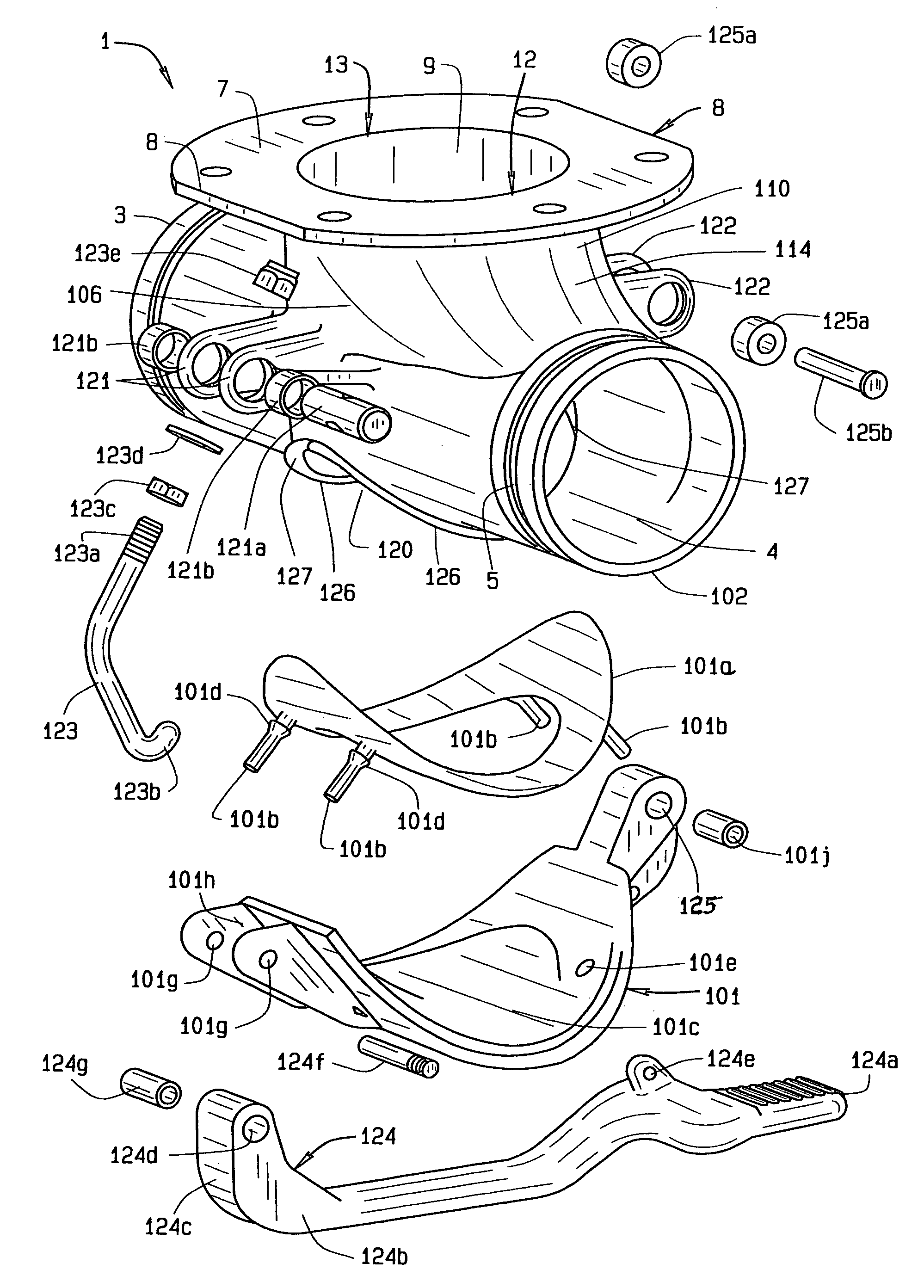
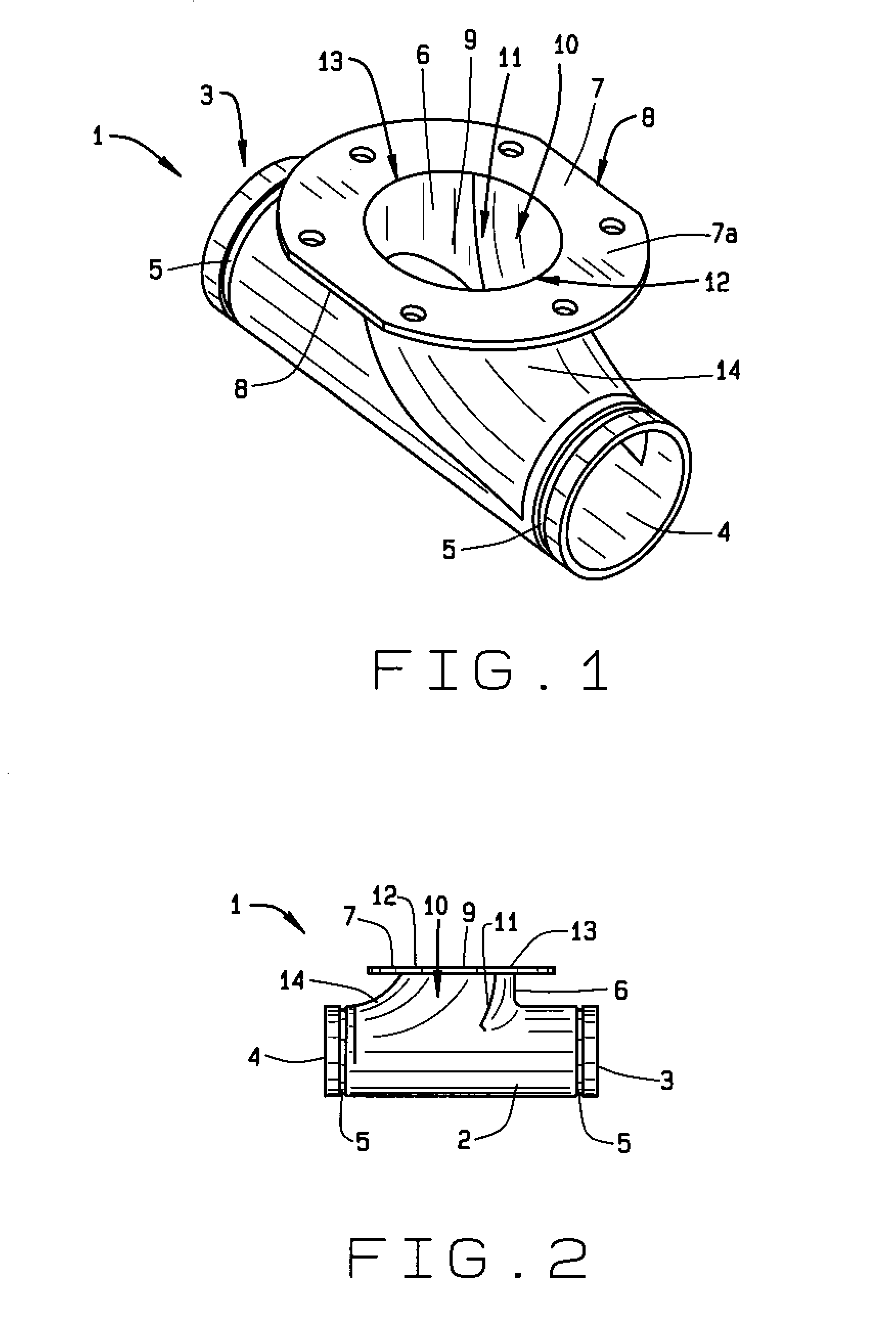
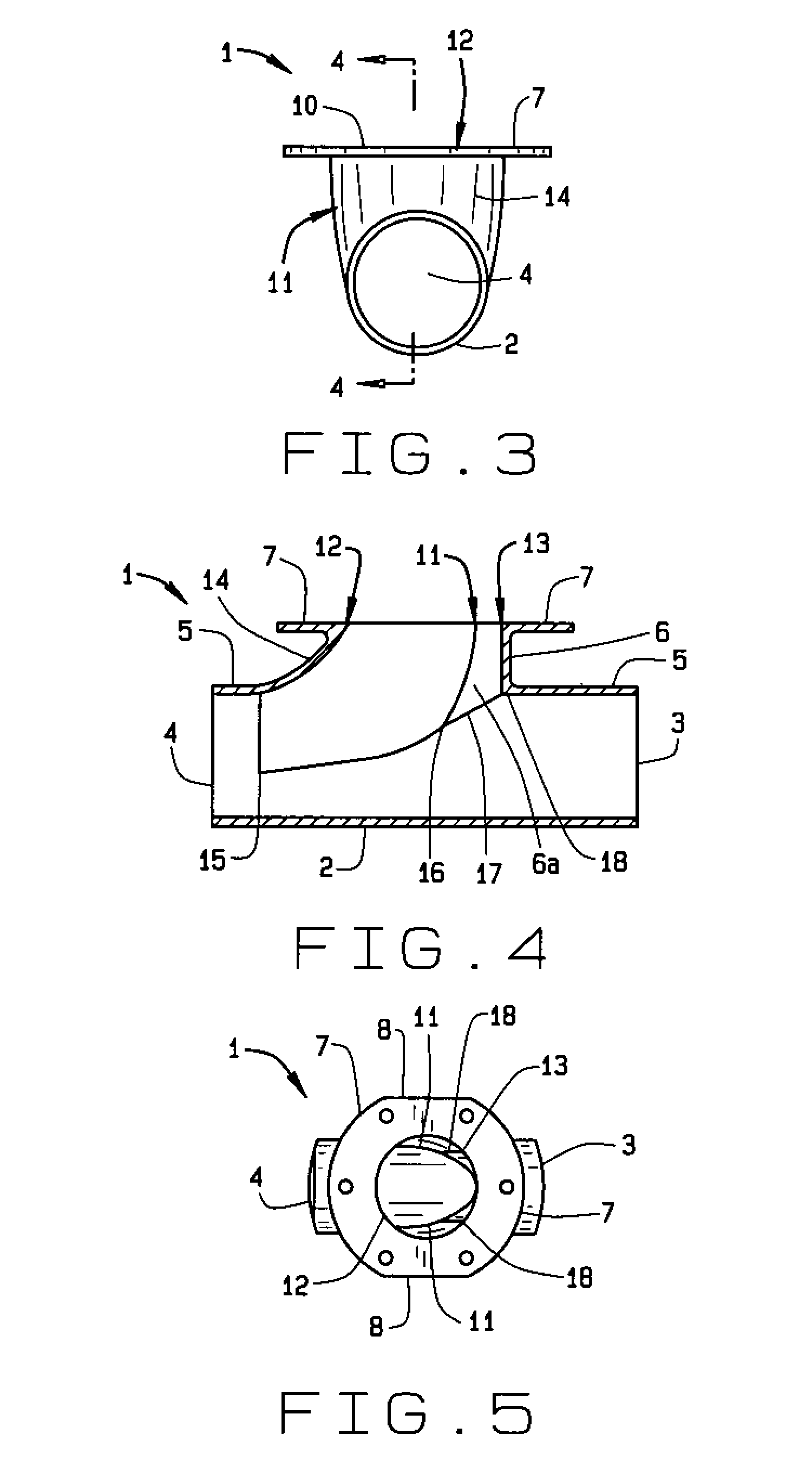
[0054]In referring to the drawings, FIG. 1 shows an integral tee, generally known as a hopper tee, of the present invention 1 in a perspective view. The present invention has a generally transverse hollow pipe, hereinafter horizontal pipe 2, round in cross section and of a known diameter. The horizontal pipe has two opposed ends, one end being an inlet 3 that receives material sent into the hopper tee under pneumatic pressures and the opposite end being an outlet 4 that discharges material from the inlet and material unloaded from a hopper, or bin, into the hopper tee. The inlet and the outlet each have a perimeter slot 5 for coupling the invention 1 into a pneumatic system for unloading. The coupling slots 5 generally extend around the entire circumference of the lower pipe proximate the inlet and the outlet.

[0055]Generally centered upon and perpendicular to the horizontal pipe, the fluted hopper tee 1 has a vertically directed hollow pipe, hereinafter vertical pipe 6. The horizont...


PUM


Abstract

A directional hopper tee has a fluted interior vertical pipe that merges into a horizontal pipe. The vertical pipe has an opening that connects to a hopper to receive bulk material, or product, and a horizontal pipe centered upon the end of the vertical pipe. The horizontal pipe has an inlet that also receives bulk material and pressurized air from ahead of the hopper and an opposite outlet that discharges the bulk material from the hopper tee. The vertical pipe has a flange that abuts the hopper and an opening in the flange that matches the opening of a valve on the hopper itself. At the opening, the vertical pipe begins to turn towards the outlet of the lower pipe with an internal flute. The flute begins immediately at the flange resulting in a vertical pipe with a curved shape towards the outlet and a square shape towards the inlet. The present invention raises the ground clearance of the horizontal pipe by at least an inch resulting in a hopper tee that clears at least 7 inches above the ground. The hopper tee of the invention also unloads at least 15% more product per minute at temperatures closer to product temperature. Alternate embodiments of the present invention provide a reinforced flange, a drop tee, and a low profile drop tee. The present invention aids in the unloading of bulk materials from various haulers.

Description

CROSS REFERENCE TO RELATED APPLICATION[0001]This non-provisional application claims priority to the provisional application having Ser. No. 61 / 030,777 filed on Feb. 22, 2008 and is commonly owned by the same inventor. This application is related to U.S. Pat. No. 6,786,362 from the same inventor.BACKGROUND OF THE INVENTION[0002]This invention relates generally to hopper tees used in bulk material handling, and more specifically pertains to a directional hopper tee that blends material dropping vertically therethrough with material entering and passing through horizontally. A unique aspect of this invention is a fluted vertical pipe that begins at the flange. The invention is especially useful for accelerating the unloading of a tank trailer hauling granular bulk material at higher ground clearance.[0003]Hoppers, or tank trailers, regularly transport bulk commodities such as industrial and food products. When the hopper, or tank trailer, reaches its destination, the bulk commodity is ...

Claims


Application Information

Patent Timeline
Patent Type & Authority Patents(United States)
IPC IPC(8): F16L41/00
CPCF16L41/021F16L45/00B65D90/623F16L57/06B65G53/10
Inventor SISK, DAVID E.
Owner BULK TANK
Why Eureka
Try Eureka