Turbine blade

a turbine blade and blade technology, applied in the field of turbine blades, can solve the problems of affecting so as to avoid damage to the gas turbine and maintain the service life of the turbine blad

Inactive Publication Date: 2012-01-10
SIEMENS AG
View PDF21 Cites 42 Cited by
  • Summary
  • Abstract
  • Description
  • Claims
  • Application Information

AI Technical Summary

Benefits of technology

[0008]It is therefore the object of the invention to provide a turbine blade for a gas turbine in which a combustion which takes place inside is safely avoided for maintaining the service life of the turbine blade and for avoiding damage in the gas turbine.

Problems solved by technology

It is disadvantageous to the concepts which are also known as “in-situ blade reheat” that, as a result of the mixing of cooling air and fuel in the components, the reaction partners can ignite as a result of self-ignition or flashback.
As a result of this, stable combustion processes are possibly formed inside the turbine blade so that the cooling effect of the fuel-air mixture is lost, or the component can be damaged as a result of the combustion which occurs internally.

Method used


Image

  • Turbine blade
  • Turbine blade
  • Turbine blade

Examples


Embodiment Construction

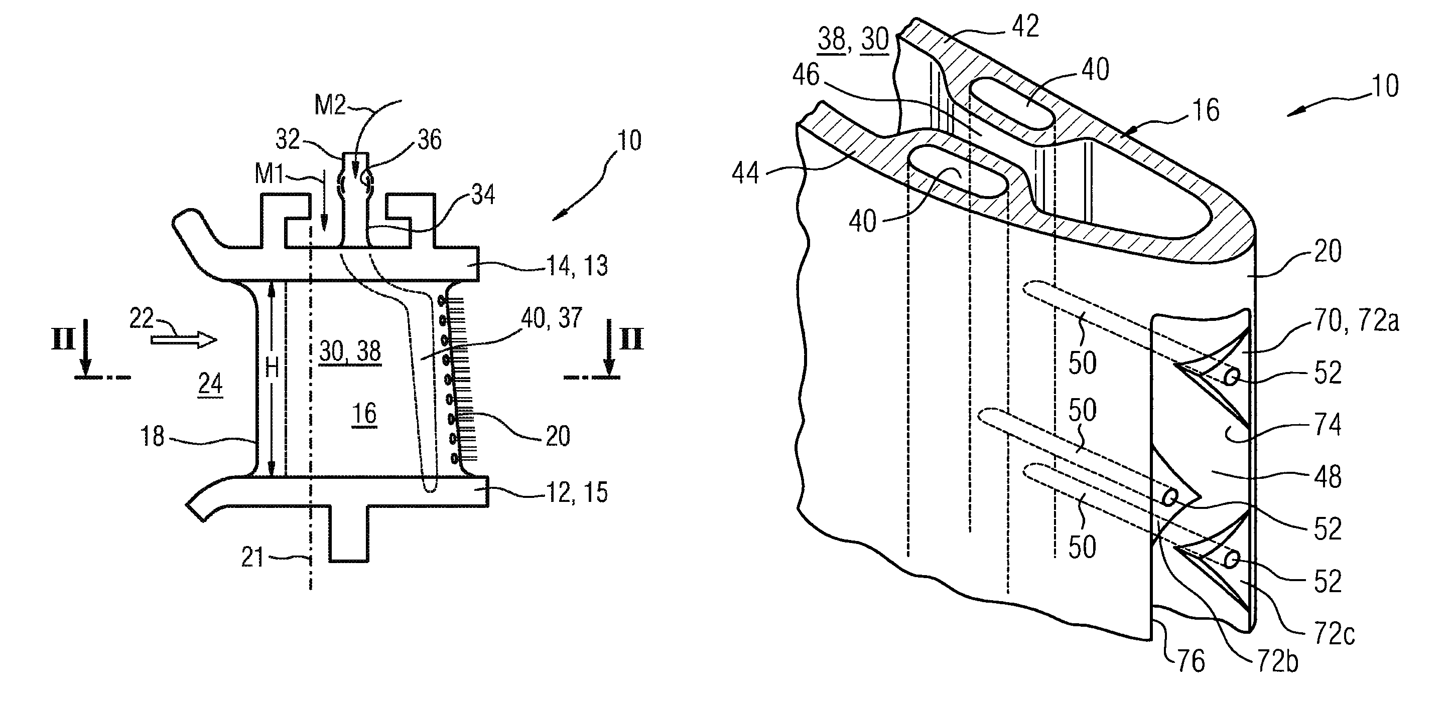
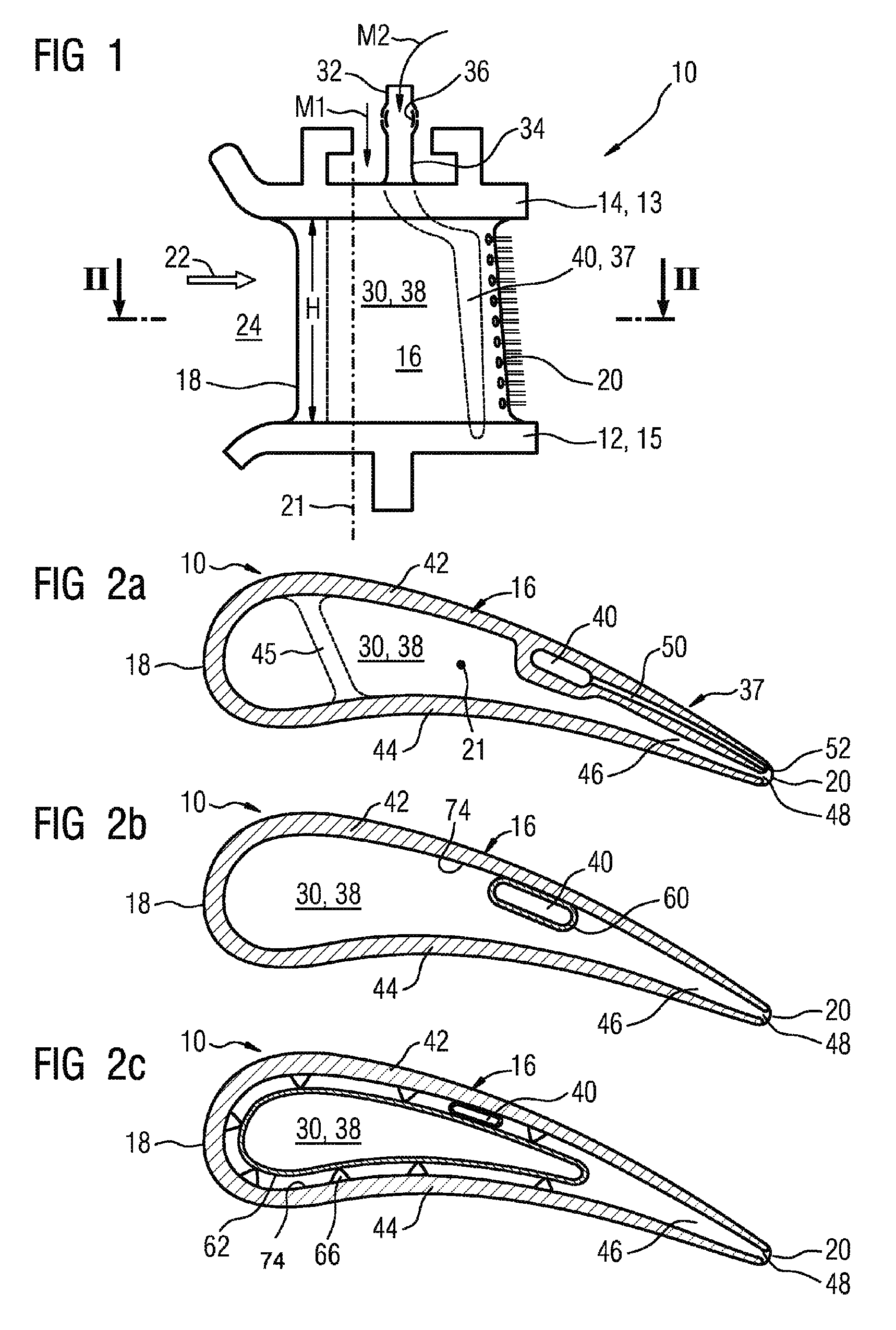
[0050]FIG. 1 shows a schematic view of a turbine blade as is used for example in one of the front stages of the turbine of for example a stationary axial gas turbine. The turbine blade 10 is represented as a stator blade and, with regard to its installed position in the gas turbine, comprises an inner platform 12, an outer platform 14 and a blade airfoil 16 which extends between the platforms in the radial direction of the gas turbine. The outer platform 14 in this case represents a root region 13 upon which the turbine blade 10, for example on a stator blade carrier, can be fastened. A tip region 15, which lies opposite the root region 13, in this case comprises the inner platform 12.

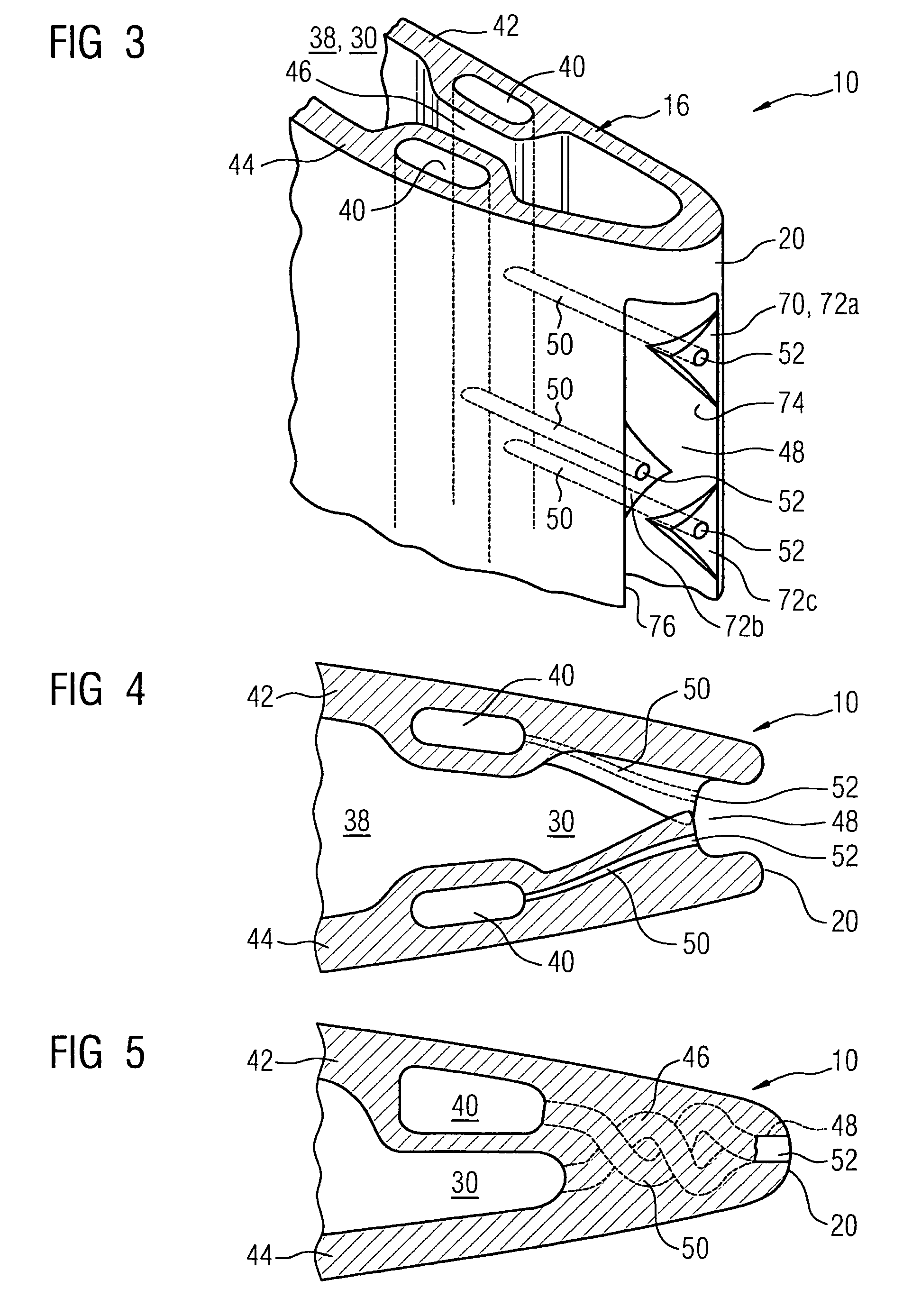
[0051]The blade airfoil 16, as FIG. 2a to FIG. 2c show, is curved in cross section in the shape of a droplet and extends from a leading edge 18 to a trailing edge 20. A blade airfoil principal axis 21 in this case extends essentially parallel to the trailing edge 21 or along the radial direction of the...


PUM


Abstract

The invention relates to a turbine blade comprising a profiled vane around which working gas flows. The working gas cross-flows a front edge of the vane and flows away on a rear edge of the vane. The vane has a first and a second channel system for guiding two media separated from the turbine blade. Combustion taking place inside is reduced in a safe manner to maintain the service life of the turbine blade and to prevent damage in the gas turbine, such that a first outlet connected to the first channel system is arranged in the region of the rear edge for blowing out the first media into the working gas and a second outlet connected to the second channel system is arranged in the region of the rear edge for blowing out the second medium.

Description

CROSS REFERENCE TO RELATED APPLICATIONS[0001]This application is the US National Stage of International Application No. PCT / EP2007 / 051403, filed Feb. 13, 2007 and claims the benefit thereof. The International Application claims the benefits of European application No. 0600831.9, filed Apr. 21, 2006, both of the applications are incorporated by reference herein in their entirety.FIELD OF THE INVENTION[0002]The invention relates to a turbine blade with a profiled blade airfoil which is exposable to circumflow by an operating gas, which has a leading edge which is exposable to inflow of the operating gas and also a trailing edge on which the operating gas can flow out, and with a first passage system and with a second passage system for the separate guiding of two different media which can be fed separately to the turbine blade, wherein the first passage system leads to at least one first discharge opening, which is arranged in the region of the trailing edge, for blowing out the first...

Claims


Application Information

Patent Timeline
Patent Type & Authority Patents(United States)
IPC IPC(8): F01D5/08F04D29/58
CPCF01D5/145F01D5/186F01D9/065F02C3/16F02K3/08F01D5/187F05D2240/124F01D5/189F05D2240/122F05D2250/25F05D2260/204
Inventor BEECK, ALEXANDER R.HOFFMANN, STEFAN
Owner SIEMENS AG
Why Eureka
Try Eureka