Illuminator

a technology of illuminator and discharge tube, which is applied in the direction of cathode-ray/electron beam tube circuit elements, transit-tube circuit elements, and luminescnet screens of discharge tubes. it can solve the problems of inevitably shortening the service life of filaments, and propose any illuminator that provides an improvement in the service life of discharge tubes

Inactive Publication Date: 2006-02-28
DIGITAL ALLIANCE
View PDF7 Cites 2 Cited by
  • Summary
  • Abstract
  • Description
  • Claims
  • Application Information

AI Technical Summary

Benefits of technology

[0008]It is an object of the present invention to provide an illuminator that illuminates an object for appreciation with both of ultraviolet light and white visible light, which is configured to be capable of maintaining the service life of a discharge tube that includes filaments for emitting thermoelectrons and is used as a light source for ultraviolet light or a light source for white visible light.

Problems solved by technology

However, due to the periodic supply of the electric power to the filaments for the purpose of the periodic irradiation described above, metal of the filaments is repeatedly vaporized and restored to its original state, which causes each filament to undergo a change in the multilayer metal structure thereof, so that the service life of the filament is inevitably shortened.
However, there has never been proposed any illuminator that provides an improvement in the service life of discharge tubes over the above-described conventional illuminator.

Method used


Image

  • Illuminator
  • Illuminator
  • Illuminator

Examples


embodiments

[0042]Hereinafter, a description will be given based on embodiments.

embodiment

[Embodiment]

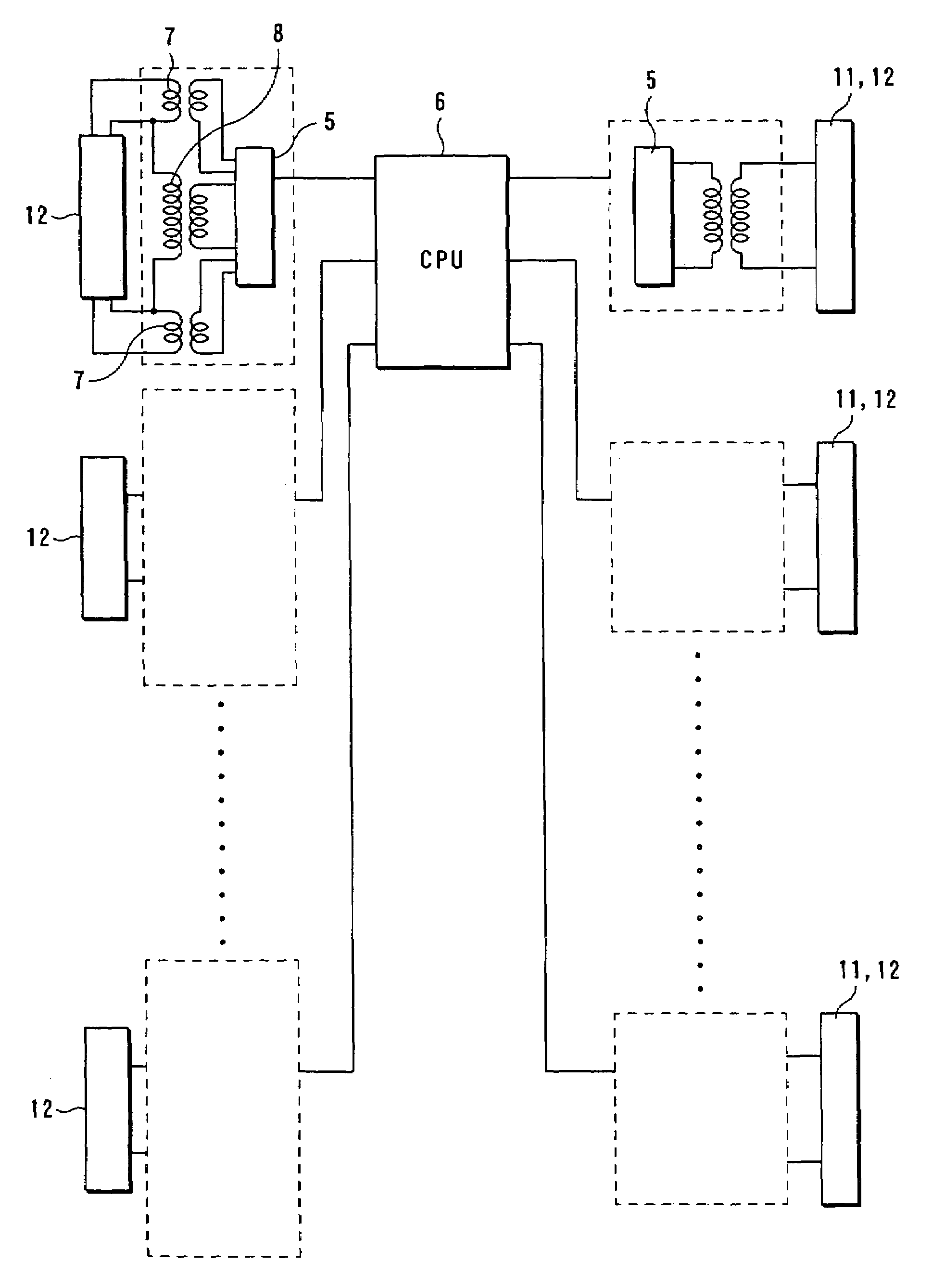
[0043]FIG. 4 shows an embodiment in which a plurality of pairs of light sources for ultraviolet light and white visible light are arranged, and a computer (CPU) 6 controls selection of a pair of light sources and periodic application of voltages from power supplies to the selected pair of light sources. In the above embodiment, it is possible to realize a variety of irradiation states by changing irradiating positions, and the order of irradiations executed therefrom.

[0044]Although the irradiating positions and order to be selected are recorded in the computer (CPU) 6, to change the recorded irradiating positions and order, it is necessary to provide instructions from outside. The instructions can be provided from a remote place by using a microcomputer or a remote control unit.

[0045]Further, although in FIG. 4, a DC is converted to an AC by an inverter 5 to apply the AC to the irradiation power supply 8, the inverter 5 is not necessarily required, if the original power ...


PUM


Abstract

An illuminator capable of increasing the service life of discharge tubes, includes a pair of an ultraviolet light-emitting discharge tube and a white visible light-emitting discharge tube that are alternately and periodically placed in a lighted state and an unlighted state, such that a state of illumination using only one of the discharge tubes is realized in at least part of a time domain during the repetition period. The illuminator includes a hot-cathode tube used for at least one of the discharge tubes, the hot-cathode tube being arranged in a state where a heating power supply for heating filaments, and an illuminating power supply for enabling motion of thermoelectrons within the hot-cathode tube and at the same time periodic repetition of the lighted state and unlighted state, are capable of executing and interrupting application of voltage, independently of each other.

Description

BACKGROUND OF THE INVENTION[0001]1. Field of the Invention[0002]The present invention relates to an illuminator that illuminates an object, such as a picture, a poster, a sculpture, or the like, which is capable of showing particular colors in response to ultraviolet light.[0003]2. Description of the Related Art[0004]Recently, a coating material is produced which emits or reflects white visible light within a predetermined wavelength region in response to irradiation of ultraviolet light. When an object for appreciation, such as a picture, a poster, a sculpture, or the like, is coated with the coating material, and irradiated with ultraviolet light, colors different from original colors of the object are caused to appear so as to cause the object to emerge in a varied status before an appreciator or a viewer.[0005]Further, there has been proposed an illuminator configured such that the white visible light and ultraviolet light are repeatedly and periodically turned on and off in ord...

Claims


Application Information

Patent Timeline
Patent Type & Authority Patents(United States)
IPC IPC(8): H01J7/44H01J17/20H05B41/24H01J1/62H05B37/02H05B41/234H05B41/36
CPCH05B41/234
Inventor ABIKO, AKIO
Owner DIGITAL ALLIANCE
Why Eureka
Try Eureka