Chest compression apparatus for cardiac arrest

a compression apparatus and cardiac arrest technology, applied in the field of medical devices, can solve the problems of limited success of devices, and large and heavy devices, and achieve the effect of enhancing blood flow

Inactive Publication Date: 2012-01-10
DECA MEDICS
View PDF40 Cites 6 Cited by
  • Summary
  • Abstract
  • Description
  • Claims
  • Application Information

AI Technical Summary

Benefits of technology

[0027]It is an objective of the present invention to provide an apparatus having a flexible belt which wraps around the chest of a cardiac arrest patient. The apparatus tightens the belt while depressing the chest, the combination of which raises the intrathoracic pressure, enhancing blood flow.

Problems solved by technology

However, the methods presently in use, and the devices currently in use, for promoting blood flow by the application of an external force are directed toward only one of the two mechanisms.
This device is large and heavy, and is dependent upon a compressed fluid for driving power.
This device was limited in its success due to complexity which requires trained personnel to use it.
This device, like many others using a chest compression design, is large and heavy.
The Newman device is not readily portable, in addition to having substantial complexity.
The central shaft attached to the cup may be compressed beyond the lips of the cup and bruise or otherwise injure the patient due to the concentration of force on the patient by the shaft tip.

Method used


Image

  • Chest compression apparatus for cardiac arrest
  • Chest compression apparatus for cardiac arrest
  • Chest compression apparatus for cardiac arrest

Examples


Embodiment Construction

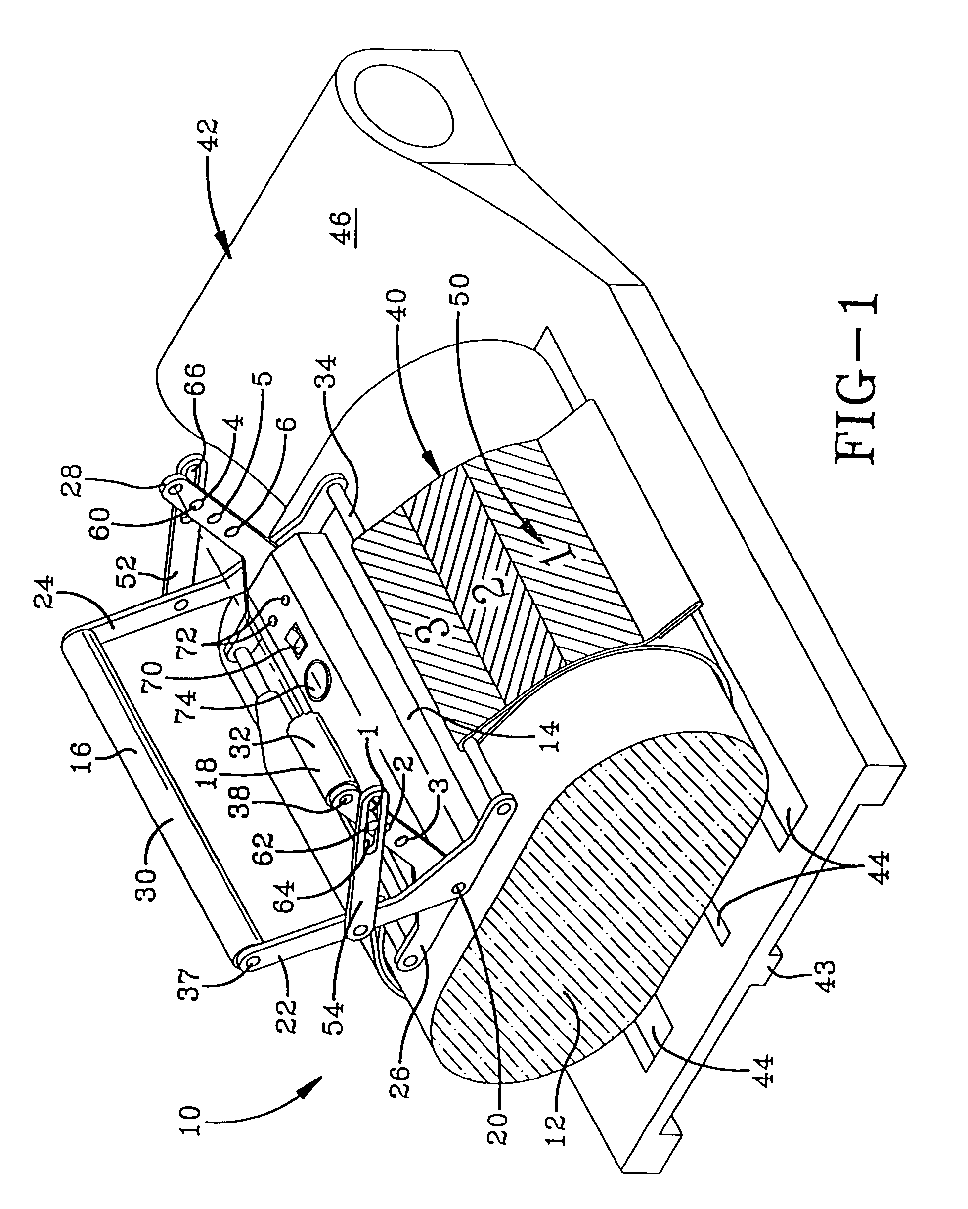
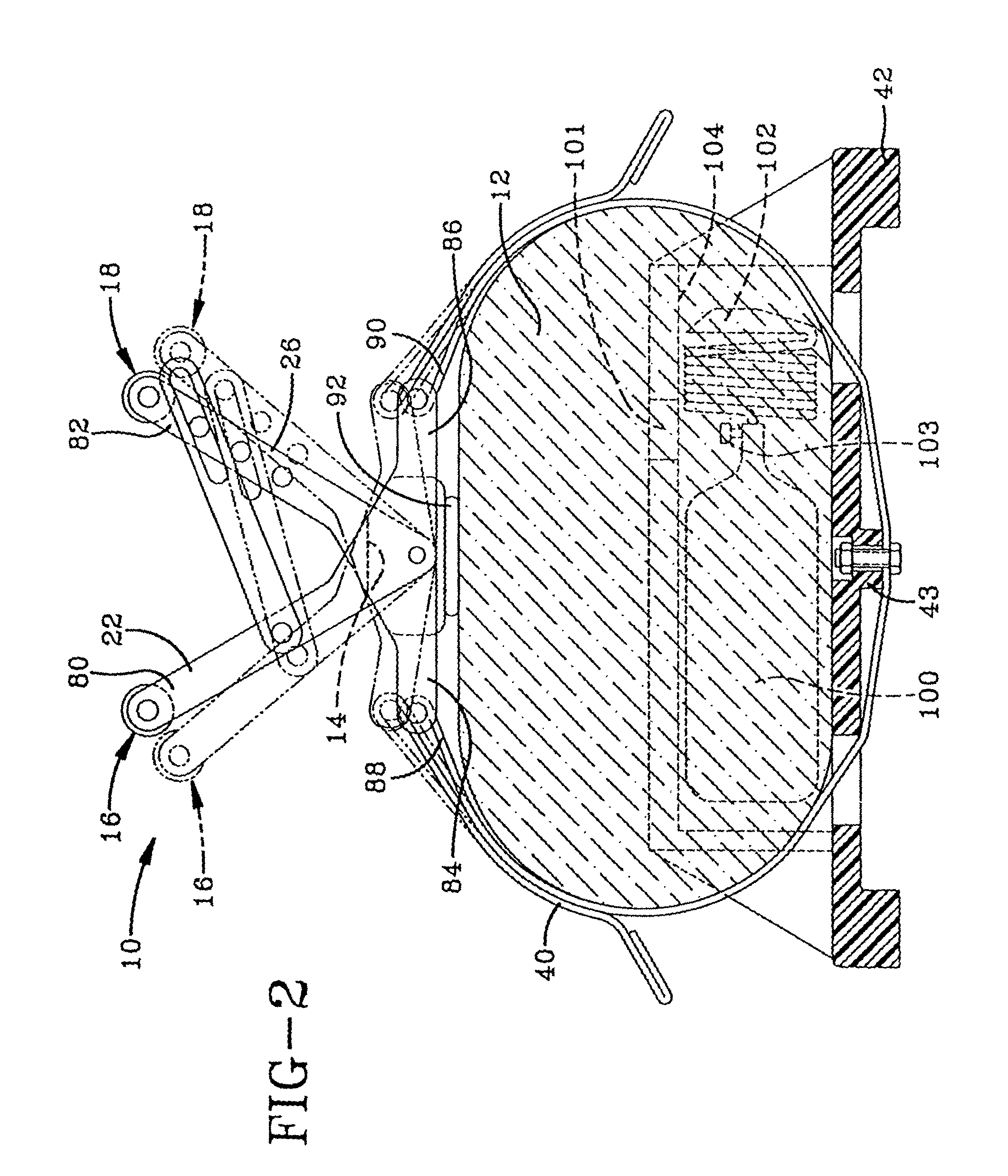
[0046]FIG. 1 shows the apparatus10, which is an embodiment of the invention, in its operable position on and around a patient's chest 12. The base 14 is a semi-rigid (preferably plastic) plate or block, preferably having a cushioned outer surface contoured to seat against the central region of the patient's chest 12 near the sternum. The sole 92 of the base 14 is seated against the upper surface of the chest 12 and may have an adhesive pad 500 (shown in FIG. 16) or a suction cup 502 (shown in FIG. 17) to adhere to the chest 12 so that pulling on the base 14 will cause the chest 12 to be pulled for decompression.

[0047]The base 14 contains a switch 70 and a pair of lights 72. Additionally, the base 14 contains a battery, a battery charge indicator and a sound generator (not visible in FIG. 1) which sound generator emits an audible, periodic signal. The visible and audible signals indicate the frequency to a rescuer of a compressive force he or she is to apply to the apparatus 10. One ...


PUM


Abstract

The invention is an apparatus for increasing intrathoracic pressure for resuscitating cardiac arrest patients. The apparatus comprises a flexible, substantially inelastic belt wrapped around the patient's chest and attached to a force converter. The force converter converts a downwardly directed force into a chestward resultant, which depresses the sternum, and two belt tightening resultants. The force converter comprises a pair of arm assemblies, each having a pair of spaced arms, which are pivotably mounted to a base. The base is positioned near the patient's sternum and the ends of the belt attach to one end of each arm assembly. The opposite, handle ends of the arm assemblies are depressed toward the chest causing tightening of the belt and compression of the chest cavity.

Description

[0001]The present application is a continuation of U.S. patent application Ser. No. 09 / 818,102, filed Mar. 27, 2001 now U.S. Pat. No. 6,645,163, which is (1) a division of U.S. patent application Ser. No. 09 / 059,497, filed Apr. 13, 1998, and issued as U.S. Pat. No. 6,234,984 on May 22, 2001, which was a continuation of U.S. patent application Ser. No. 08 / 573,465, filed Dec. 15, 1995, and issued as U.S. Pat. No. 5,738,637 on Apr. 14, 1998, and (2) a continuation of U.S. patent application Ser. No. 09 / 546,519, filed Apr. 11, 2000, and issued as U.S. Pat. No. 6,325,771, on Dec. 4, 2001, which was a continuation of U.S. patent application Ser. No. 09 / 059,497, filed Apr. 13, 1998, and issued as U.S. Pat. No. 6,234,984 on May 22, 2001, which was a continuation of U.S. patent application Ser. No. 08 / 573,465, filed Dec. 15, 1995, and issued as U.S. Pat. No. 5,738,637 on Apr. 14, 1998.TECHNICAL FIELD[0002]This invention relates broadly to the field of medical devices and more specifically to...

Claims


Application Information

Patent Timeline
Patent Type & Authority Patents(United States)
IPC IPC(8): A61H31/02A61H31/00
CPCA61H31/005A61H31/007A61H31/008A61H2011/005A61H2031/002A61H2031/003A61H2201/0173A61H2201/018A61H2201/5048A61H2201/5061A61M16/06A61M2202/0208A61M2209/08Y10S601/06A61N1/3904A61H31/00
Inventor KELLY, KEVIN A.LACH, THOMAS E.LACH, RALPH D.HANDSHY, ARTHUR W.
Owner DECA MEDICS
Why Eureka
Try Eureka