
System for noise reduction in circuits

a circuit and noise reduction technology, applied in the field of electrical circuitry, can solve the problems of digital circuits generating noise, electrical “noise” is a problem for analog and digital circuit designers, noise decreases the overall signal, etc., and achieves the effect of reducing the overall noise generated by circuit components

Inactive Publication Date: 2012-01-10
MONTEREY RES LLC
View PDF10 Cites 11 Cited by
  • Summary
  • Abstract
  • Description
  • Claims
  • Application Information

AI Technical Summary

Benefits of technology

[0009]According to embodiments of the invention, additional circuit components, referred to as “anti-circuits,” are included in some circuits, which reduce overall noise generated by circuit components.

Problems solved by technology

Electrical “noise” is a problem for analog and digital circuit designers.
Digital circuits generate noise when they switch between high and low levels.
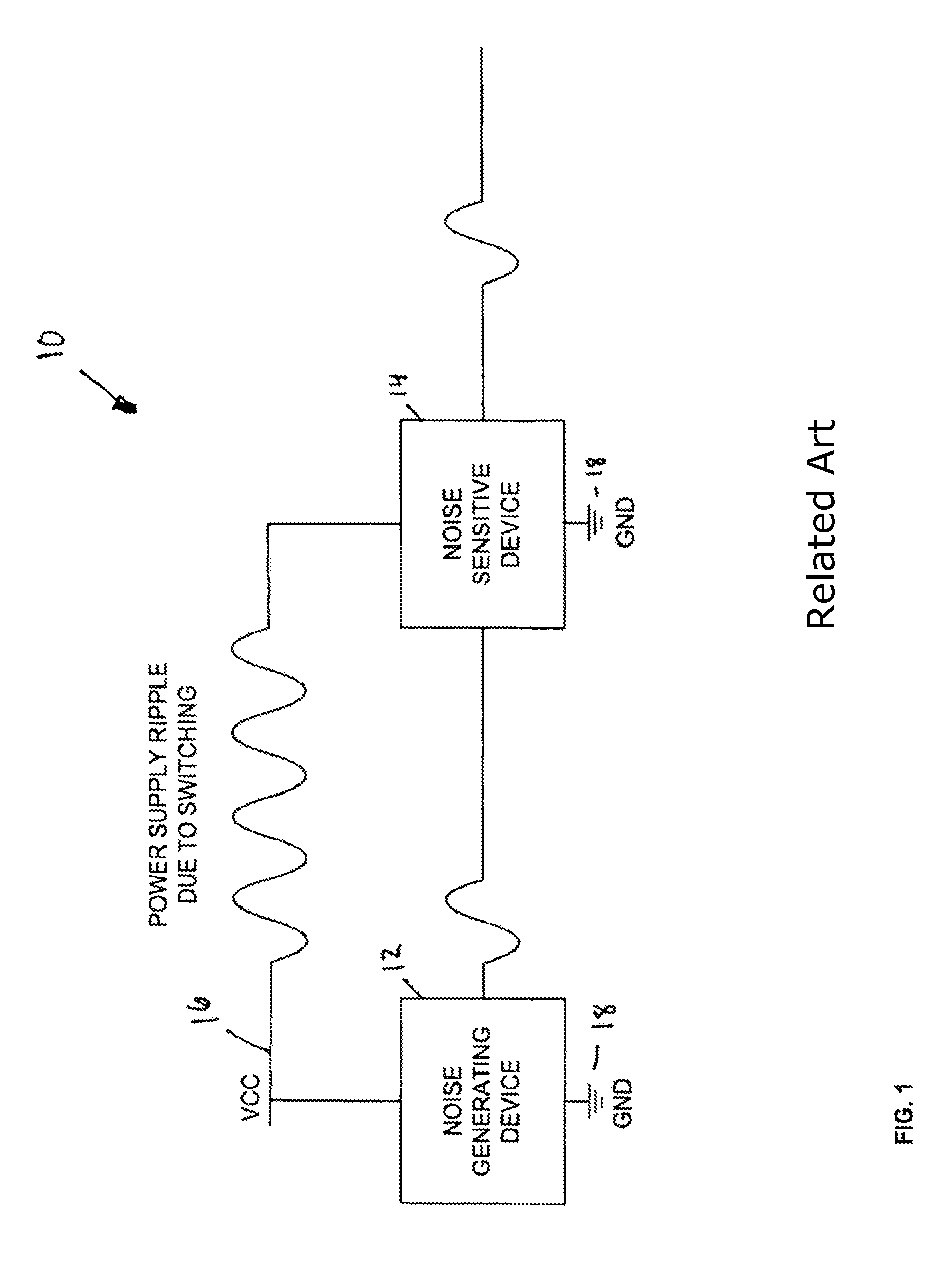
Noise decreases the overall signal to noise ratio (SNR) for the system 10, which reduces the quality of the output.
Although it is possible to minimize or eliminate noise that is generated periodically and in a predetermined manner, by using various techniques, noise generated by switching digital circuits typically does not follow any set pattern and is not known what noise will be generated before it is generated, and therefore cannot be predicted, nor cancelled.
Analog blocks tend to be quite sensitive to noise, and power-supply ripple may be directly visible on analog outputs, causing lower SNR and relatively poor performance.
Having separate supplies and grounds tend to improve the noise problems, but generally do not eliminate them.
These techniques may be helpful but often are insufficient, especially at high frequency.

Method used


Image

  • System for noise reduction in circuits
  • System for noise reduction in circuits
  • System for noise reduction in circuits

Examples


Embodiment Construction

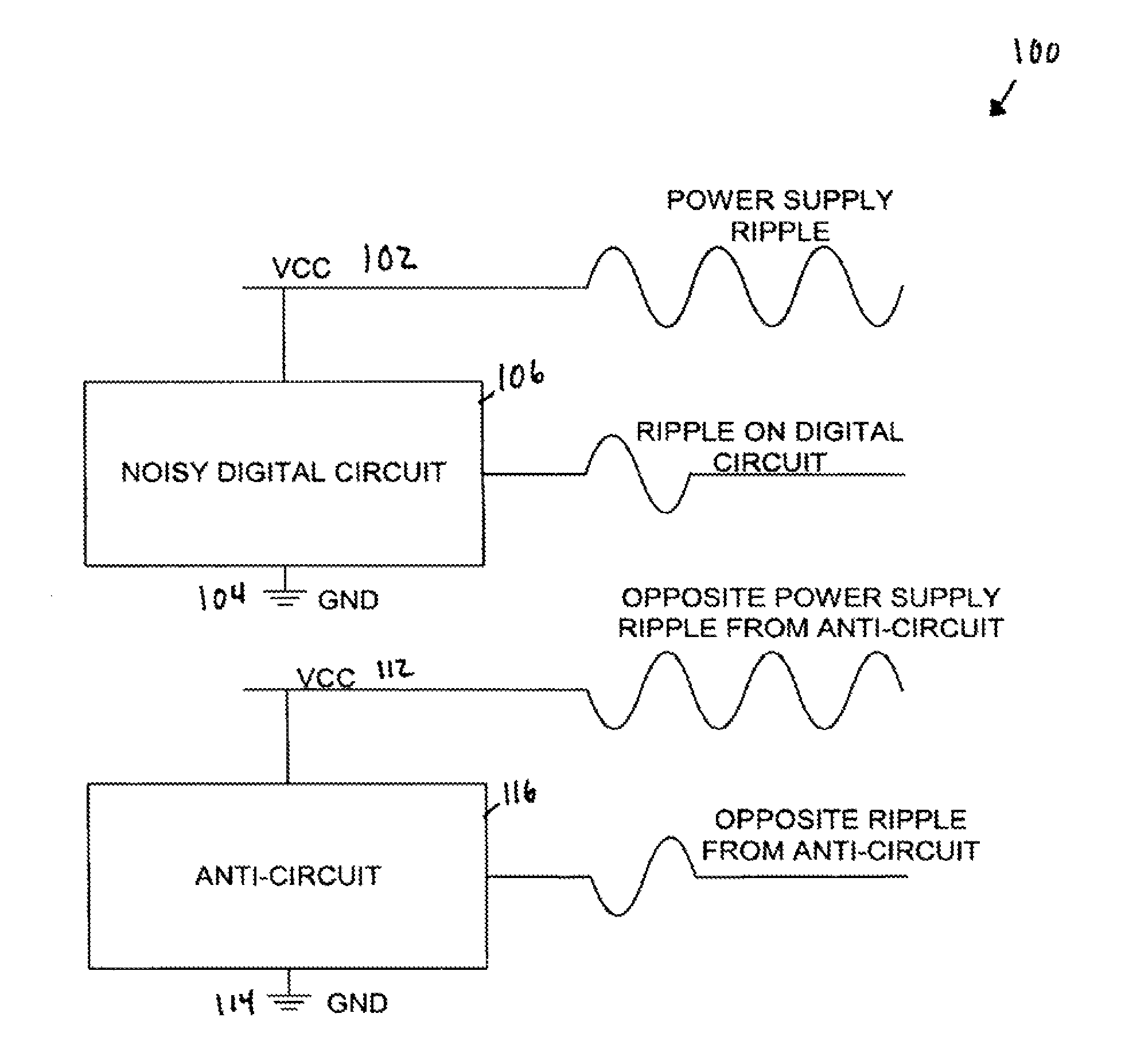
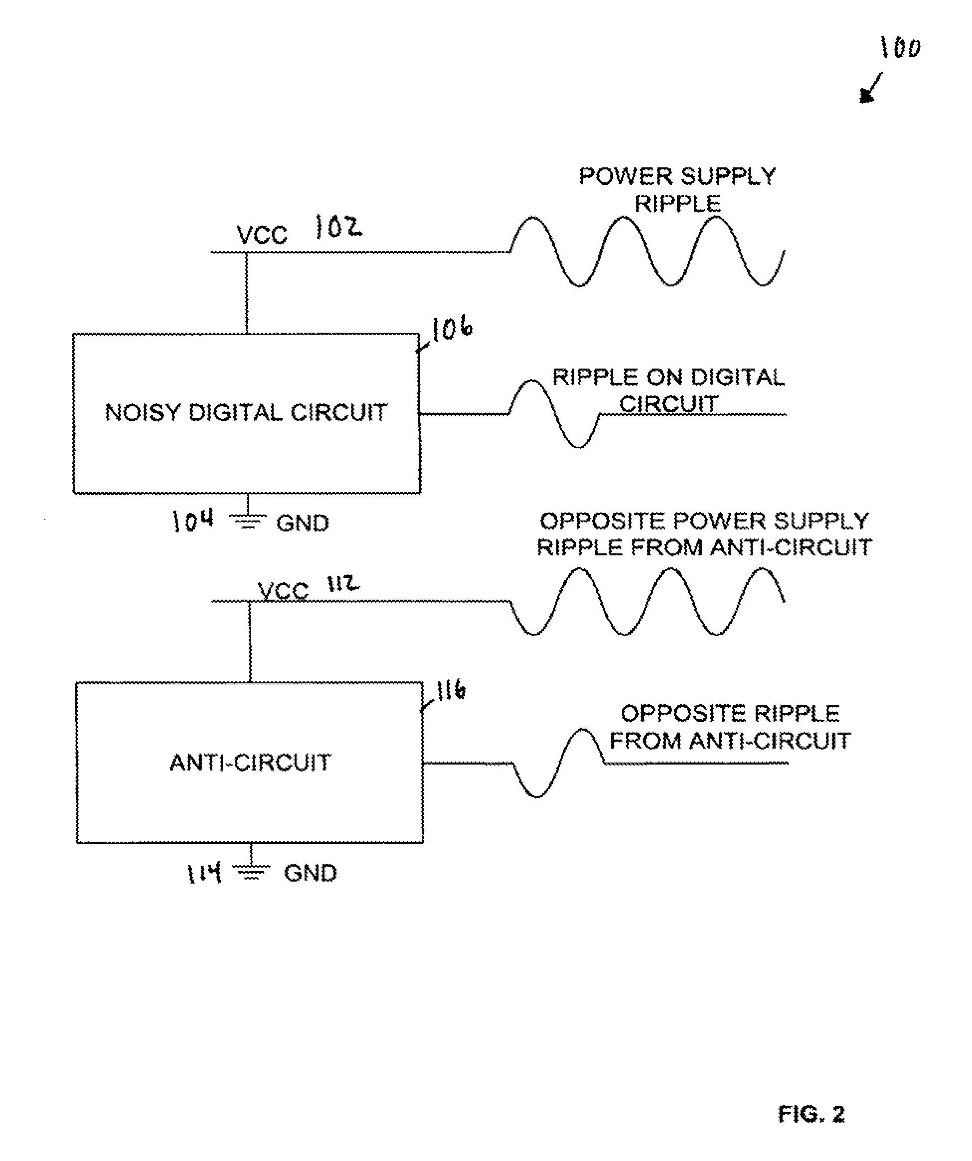
[0018]Embodiments of the invention are directed toward including “anti-circuits” in devices having noisy electric circuits. Both the noisy circuits and anti-circuits can be connected to the same power supply line. As a noisy circuit generates a signal that produces noise on the power supply line, its corresponding anti-circuit generates an opposite signal of “anti-noise.” The noise and anti-noise destructively interfere with one another, which allows the power supply line to be relatively unaffected by noise. The power supply line can then connect to more noise-sensitive analog circuitry than would otherwise be possible.

[0019]An embodiment of noise reducing system elements using an anti-circuit is shown in FIG. 2. A system 100 includes two power supplies 102, 112, and two ground references 104, 114. The power supply 102 and the ground reference 104 supply operating voltages to a noisy digital circuit 106. Similarly, the power supply 112 and the ground reference 114 supply operating ...


PUM


Abstract

Disclosed is an improved noise reducing apparatus using an anti-circuit, including a digital logic circuit and a digital anti-circuit corresponding to the digital logic circuit. The digital anti-circuit functions to cancel noise generated by the digital logic circuit. The anti-circuit includes logic to generate a similar number of switching edges as the logic circuit, where the anti-circuit edges are in the opposite direction as the logic circuit. The anti-circuit may have a circuit structure close to that of the noisy circuit, or can be formed of components different in structure but generating an output pattern similar to (and opposite from) the noisy circuit. In some embodiments, the differently structured components can include a state machine coupled to a memory or look-up-table.

Description

[0001]The present application is a continuation of U.S. patent application Ser. No. 10 / 860,856, filed Jun. 3, 2004, which claims priority to U.S. Provisional Patent Application No. 60 / 475,847, filed Jun. 3, 2003.TECHNICAL FIELD[0002]This disclosure relates generally to electronic circuitry and, in particular, to a system for reducing noise in electrical circuits caused by digital sub-circuit components.BACKGROUND OF THE INVENTION[0003]Electrical “noise” is a problem for analog and digital circuit designers. This is particularly true for mixed signal circuits that include both digital and analog sub-circuits. FIG. 1 illustrates an exemplary conventional system 10 having both digital and analog blocks operating simultaneously. This system 10 includes a digital logic block 12 (noise generating device), an analog block 14 (noise sensitive device), a power supply 16, and a ground 18. An output from the analog block 14 is an output from the system 10.[0004]Noise or voltage spikes are illu...

Claims


Application Information

Patent Timeline
Patent Type & Authority Patents(United States)
IPC IPC(8): H03K17/80H02J3/00
CPCH03B29/00H03K19/00346H03K19/00392
Inventor BEARD, PAUL
Owner MONTEREY RES LLC
Learn More