System and method for cable resistance cancellation

a technology of resistance cancellation and cable, applied in the direction of three-or-more-wire dc circuits, ac network voltage adjustment, instruments, etc., can solve the problems of unneeded bulk and weight for users, unfavorable upgrade of power supplies, and unfavorable use of power supplies, so as to reduce the wire gauge of the main power wires and tight output accuracy.

Inactive Publication Date: 2012-01-10
IGO INC
View PDF9 Cites 10 Cited by
  • Summary
  • Abstract
  • Description
  • Claims
  • Application Information

AI Technical Summary

Benefits of technology

[0006]The present invention achieves technical advantages as a method for cable resistance cancellation. One embodiment of the invention utilizes a single remote sense line and a simple cable resistance cancellation network in a power supply unit to compensate for the total cable voltage drop, while maintaining tight output accuracy. By completely compensating for the voltage drops, the wire gauge for the main power wires can be reduced, thereby allowing the use of smaller diameter cables.

Problems solved by technology

For an external power supply, the output cable wire resistance will cause load regulation issues, as the current drawn from the load varies.
Lack of voltage drop compensation means that output cables have to be sized with large AWG wire to minimize the IR drops and that open circuit (no load) output voltage had to be programmed high to minimize the effects of the drops.
Adding a second remote sense wire and two more tip connector pins increase the weight and size of the cable and tip connector, thereby adding unneeded bulk and weight for a user.
This meant that no passive tip could force the base unit output voltage below the preset minimum (thus, no ability to upgrade the power supply to operate over a wider voltage range other than changing the base unit).
This puts a portion of the feedback loop outside the base unit, making loop compensation more difficult.
This external low frequency pole would make loop compensation difficult and degrade the transient response of the base unit.
Also, the distributed capacitance of the cable itself produces a similar pole at higher frequencies, again contributing to problems in compensating the feed back loop.

Method used


Image

  • System and method for cable resistance cancellation
  • System and method for cable resistance cancellation
  • System and method for cable resistance cancellation

Examples


Embodiment Construction

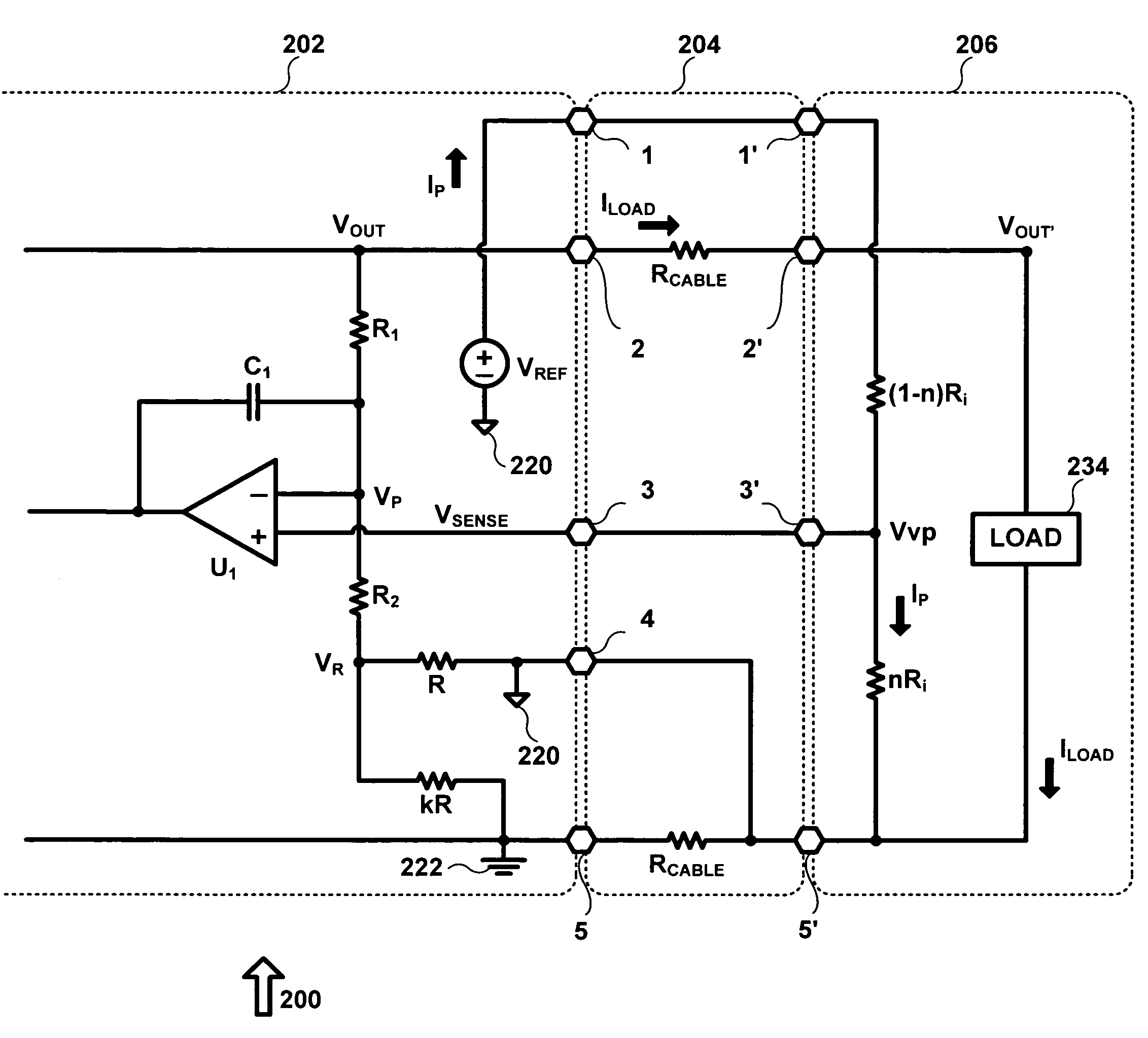
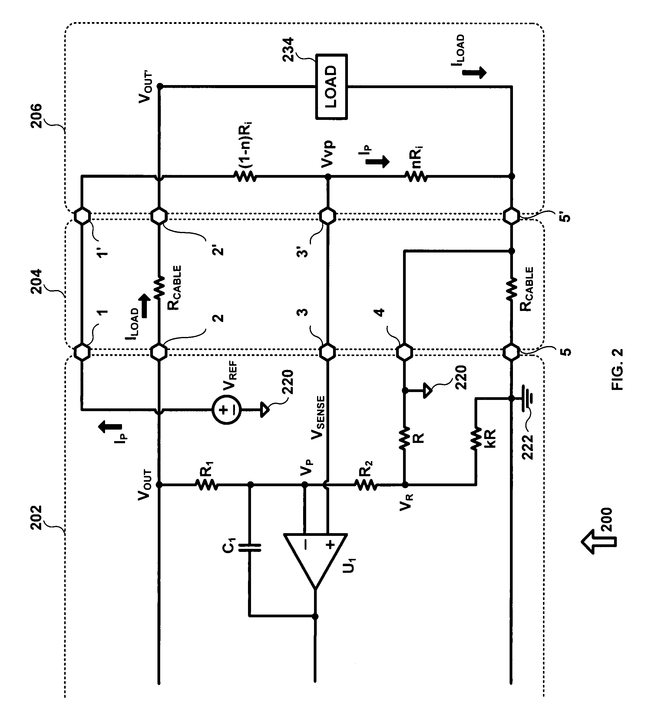
[0010]Referring now to FIG. 2, there is shown at 200 a diagram of an output voltage programming system in accordance with an exemplary embodiment of the present invention. Voltage programming system 200 compensates for cable voltage drop, while maintaining tight voltage output accuracy. Voltage programming system 200 is comprised of base unit 202, cable 204, and tip 206.

[0011]Base unit 202 contains a standard voltage comparator / integrator amplifier U1 with feedback from the internal Vout signal. The Vout feedback is attenuated by the resistor network of R1 and R2. The other input to this amplifier is from a resistor divider in tip 206. The tip resistor divider sets the output voltage for the tip output connector. Also in base unit 202 is voltage reference, Vref, that is used to provide a current to tip 206 in order to establish 2.5V at the top of the tip resistor divider. This current will vary as discussed later based on the total value of the tip resistor divider. Base unit 202 ha...


PUM


Abstract

A method for cable resistance cancellation. A single remote sense line and a simple cable resistance cancellation network are leveraged in a power supply unit to compensate for the total cable voltage drop, while maintaining tight output accuracy. By completely compensating for the voltage drops, the wire gauge for the main power wires can be reduced, thereby allowing the use of smaller diameter cables.

Description

FIELD OF THE INVENTION[0001]The present invention is generally related to power supply cables, and more specifically to power supply cable resistance cancellation.BACKGROUND OF THE INVENTION[0002]For an external power supply, the output cable wire resistance will cause load regulation issues, as the current drawn from the load varies. Cable wire gauge and length will also affect the output voltage accuracy as the resistance of the load changes. Traditionally, in order to maintain tight output accuracy, the output cable and circuits have incorporated two remote sense wires which are able to compensate for the total cable voltage drop. Another technique used is lowering the gage (increasing the diameter) of the output wire to lessen the effects of the voltage drop. Lack of voltage drop compensation means that output cables have to be sized with large AWG wire to minimize the IR drops and that open circuit (no load) output voltage had to be programmed high to minimize the effects of th...

Claims


Application Information

Patent Timeline
Patent Type & Authority Patents(United States)
IPC IPC(8): G05F1/00
CPCH02J1/08
Inventor SUN, LIMING
Owner IGO INC
Why Eureka
Try Eureka