Razor blade unit with film hinge

a technology of film hinges and blades, applied in metal working devices and other directions, to achieve the effect of avoiding damage to the film hinges by unwanted overextension, no elasticity, and increasing safety during shaving

Active Publication Date: 2012-01-17
FEINTECHN EISFELD
View PDF30 Cites 51 Cited by
  • Summary
  • Abstract
  • Description
  • Claims
  • Application Information

AI Technical Summary

Benefits of technology

[0010]An essential aspect of the razor blade unit of the present invention is the position of the pivot axis which extends through the film hinge. Relative to the direction of the longitudinal axis of the handle, this axis is positioned in an area which extends from the forward (forward with respect to the shaving direction) boundary of the foam edge to the cutting edge situated closest to the foam edge. Because of the way in which the film hinge is designed, locating the pivot axis in this area offers the special advantage that the introduction of a force component via the handle in the direction toward the area of skin to be shaved does not lead to the unwanted tilting-up of the blade housing, as a result of which secure contact of the cutting edges with the area being shaved is guaranteed in all cases.
[0012]It is advantageous for the foam edge to consist of the same soft, elastomeric plastic as the damping component. The hard components of the blade housing, of the coupling section, and of the connecting section can also consist of a uniform, hard plastic, which is stronger than the soft plastic of the damping component and which comprises essentially no elasticity. As a result, all of the housing parts of the razor blade unit can be produced by a two-component plastic injection-molding process.
[0013]A preferred embodiment of the razor blade unit has a pivot-limiting sidepiece, which is attached either to the blade housing or to the coupling section and which cooperates with an opposing stop. The pivot angle around which the blade housing can pivot with respect to the coupling section can thus be restricted. This increases safety during shaving and avoids damage to the film hinge by unwanted overextension under the action of strong forces. The pivot angle is preferably limited to a range between 0° and 45°, based on the position of the blade housing with respect to the longitudinal axis of the handle.

Problems solved by technology

The two film hinges designed in this way are so flexible that they are not alone enough to guarantee the transmission, from the handle to the blade housing, of the force necessary for shaving.

Method used


Image

  • Razor blade unit with film hinge
  • Razor blade unit with film hinge
  • Razor blade unit with film hinge

Examples


Embodiment Construction

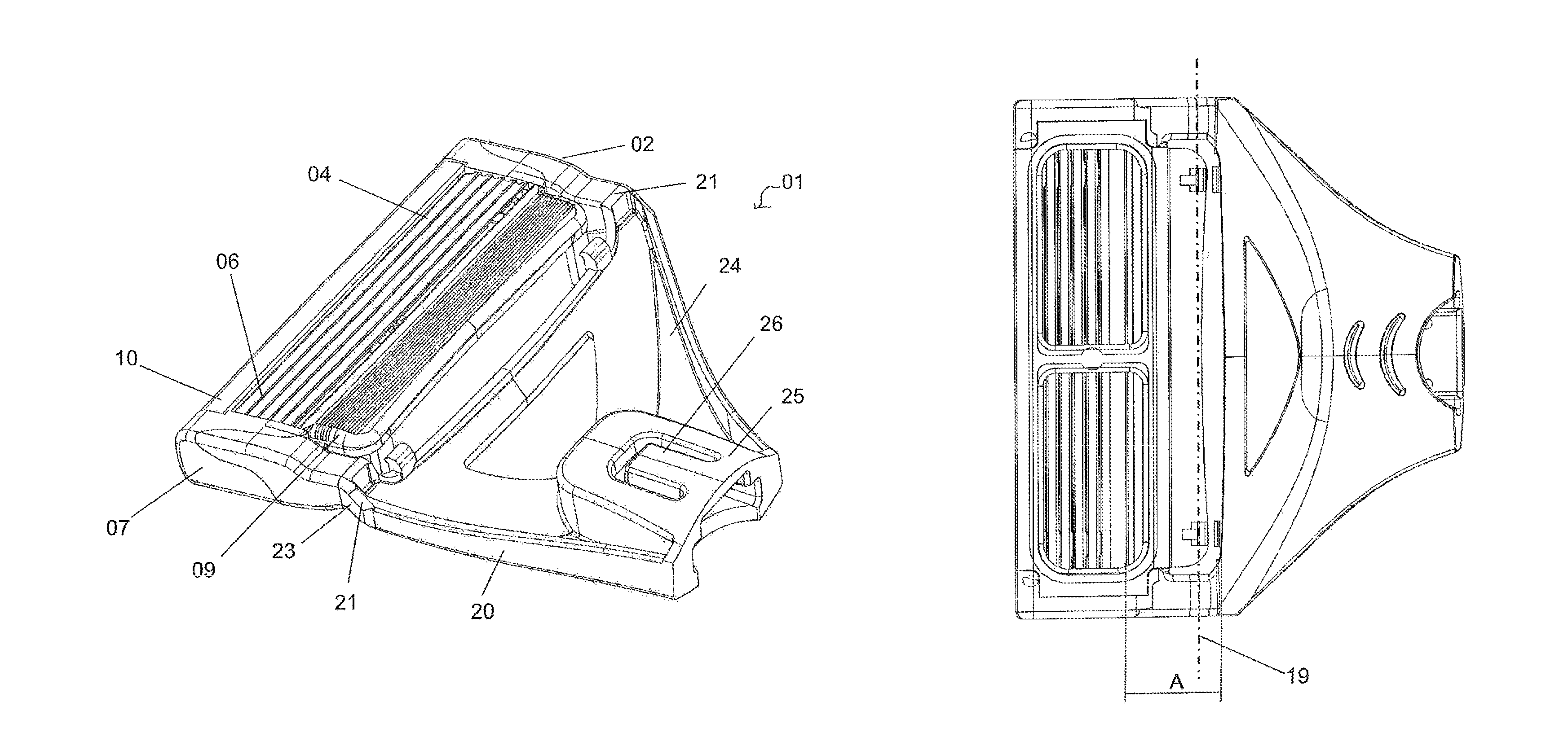
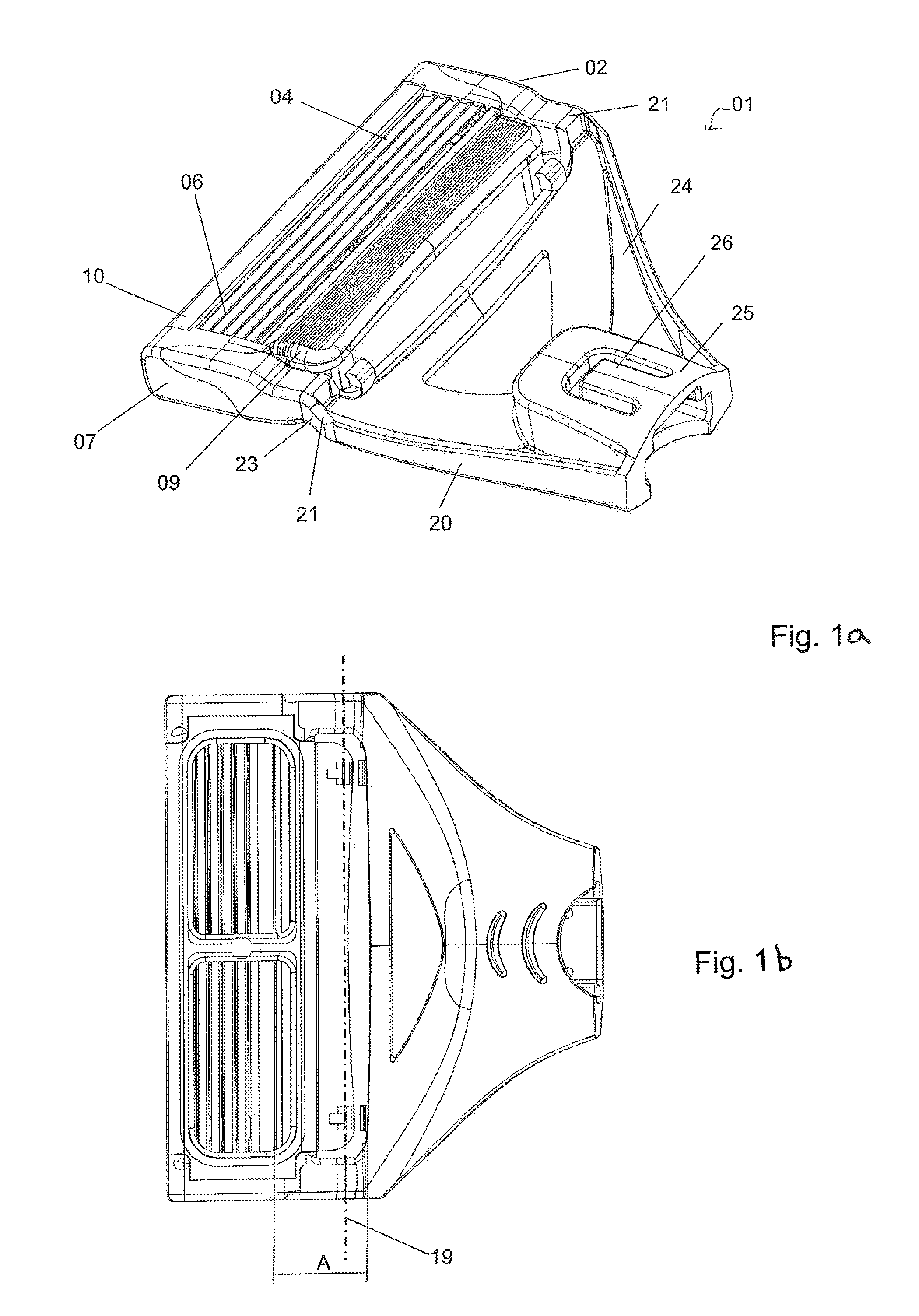
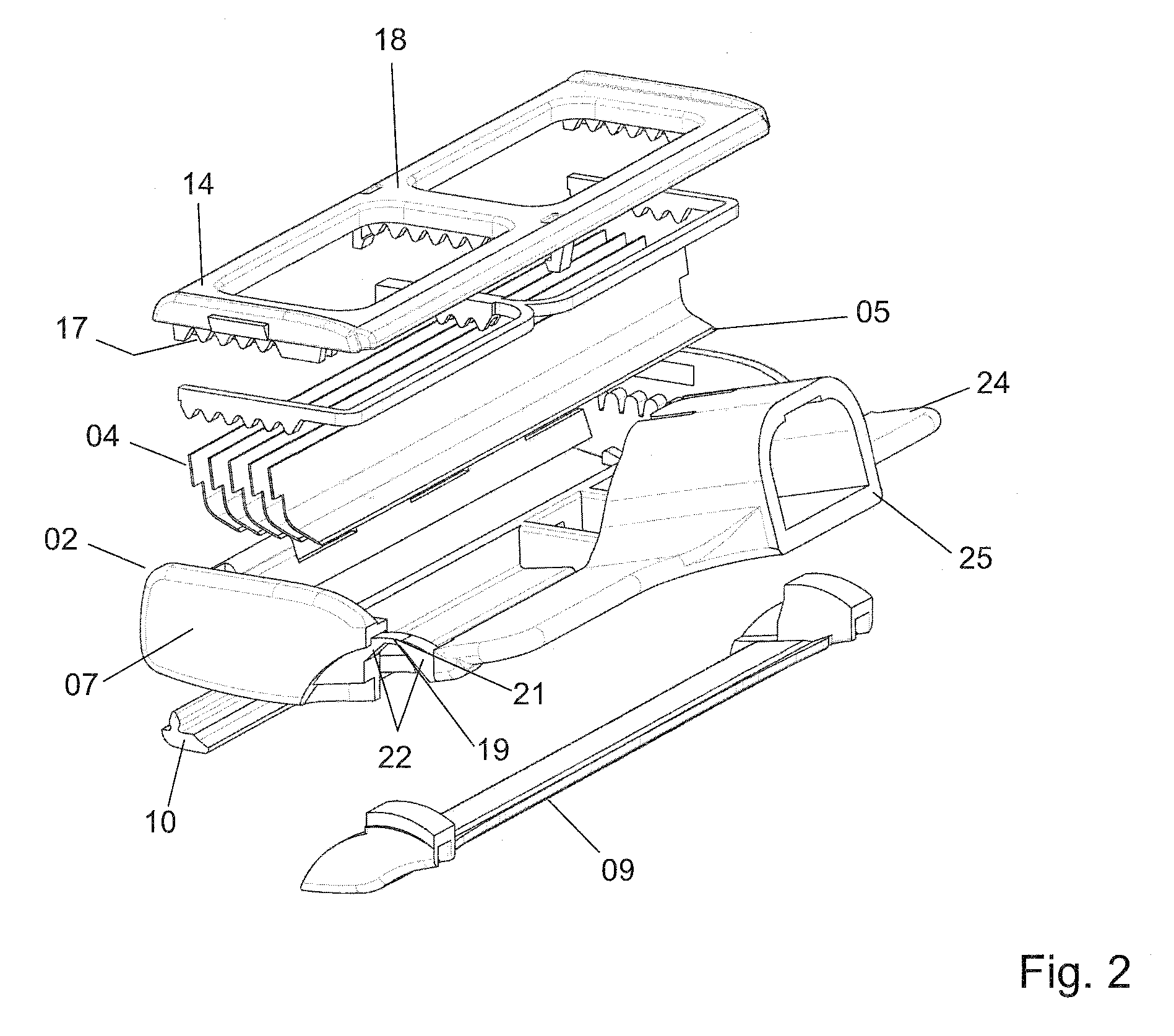
[0023]The basic design of the inventive razor blade unit is explained below on the basis of FIGS. 1a, 1b and 2, where the razor blade unit in FIGS. 1a and lb is illustrated in the assembled state as seen from the front (upper part of the figure) and from the rear (lower part of the figure), whereas FIG. 2 shows an exploded view of a slightly modified design of the razor blade unit.

[0024]The inventive razor blade unit 01 comprises a blade housing 02, which holds several blades 04. In the embodiment shown here, the blade housing 02 serves to hold a total of five blades 04, each of which comprises a cutting edge 05. Of course, more or fewer blades can be used in the razor blade unit. In the embodiment shown, the blades 04 are designed as angled blades. The area comprising the cutting edge 05 is bent over during the blade production process at an angle of preferably about 50-70°.

[0025]The blade housing 02 leaves a window 06 open in its front surface, in which the cutting edges 05 of the...


PUM


Abstract

A razor blade unit with a blade housing, in which several blades with cutting edges lying parallel to a skin contact plane are arranged, a coupling section, which can be connected preferably in a detachable manner to a handle, and a connecting section. The connecting section includes at least one film hinge between the blade housing and the coupling section, which hinge defines a pivot axis extending parallel to the skin contact plane, and an elastic damping component, which surrounds one or more sides of the film hinge and is formed both on the blade housing and on the coupling section. The razor blade unit also has a foam edge, arranged in front of the cutting edges (with respect to the shaving direction) of the blades to pretension the skin during shaving. The pivot axis extending through the film hinge is positioned between the forward boundary (with respect to the shaving direction) of the foam edge and the cutting edge lying closest to the foam edge.

Description

BACKGROUND OF THE INVENTION[0001]The present invention pertains to a razor blade unit for a razor.[0002]High-value conventional razor blade units are supported so that they can pivot with respect to the handle around a rotational or pivot axis which is perpendicular to the longitudinal axis of the handle. The skin-contact plane of the razor blade unit can thus be laid more effectively against the skin to be shaved during the shaving process.[0003]DE 297 24 245 U1 refers to, among other things, a razor blade unit in which the axis of rotation is located above the cutting edges of the blades and above the housing. DE 297 24 245 U1 also describes an axis of rotation located on the cutting edge of the second blade.[0004]EP 0 638 015 B1 describes a razor in which the axis of rotation lies either on the side of the blade unit or on the side of the blade unit opposite the razor handle relative to the shaving surface, as a result of which the axis of rotation, with respect to its location d...

Claims


Application Information

Patent Timeline
Patent Type & Authority Patents(United States)
IPC IPC(8): B26B21/52
CPCB26B21/225
Inventor DENKERT, UWERUEDE, KAI-UWE
Owner FEINTECHN EISFELD
Why Eureka
Try Eureka