Dynamic bow alignment, analysis and repair apparatus and system

a technology of analysis and repair apparatus, applied in the field of dynamic bow alignment, analysis and repair apparatus and system, can solve the problems of difficult empirical pursuit, difficult adjustment of bow tuning by traditional means, and inability to achieve optimal performance, and expose all functional anomalies

Inactive Publication Date: 2012-01-17
STAGG WESLEY
View PDF29 Cites 14 Cited by
  • Summary
  • Abstract
  • Description
  • Claims
  • Application Information

AI Technical Summary

Benefits of technology

[0005]A dynamic bow alignment, analysis and repair apparatus and system comprises an adjustable frame allowing the frame to adjust to fit any size bow. An air ram is used to controllably draw the shooting string as needed. A reference laser alignment module is mounted to a bow riser and allows a user to consistently and reliably align any bow for optimum performance based on the particularities of the selected bow subject to wear, defects and design constraints. The system removes the guesswork and allows a user to optimize any bow. A laser equipped arrow works in conjunction with the alignment module to allow the user to correctly position the shooting rest and nock indexer, and expose all functional anomalies. The system allows a user to completely quantify the performance parameters of bow performance including speed and spine tests. The system serves all major alignments and repairs.

Problems solved by technology

From the earliest times, accuracy was always an issue and the best archers developed secrets to tune their bows, but it was based on trial by error and great experience.
Of course early bows had very little to adjust compared to modern compound bows.
The modern bow has many possible adjustments and each adjustment has an effect on all the other adjustments which makes tuning the bow by traditional means a very difficult and empirical pursuit.

Method used


Image

  • Dynamic bow alignment, analysis and repair apparatus and system
  • Dynamic bow alignment, analysis and repair apparatus and system
  • Dynamic bow alignment, analysis and repair apparatus and system

Examples


Embodiment Construction

[0030]In the following detailed description of the invention, reference is made to the drawings in which reference numerals refer to like elements, and which are intended to show by way of illustration specific embodiments in which the invention may be practiced. It is understood that other embodiments may be utilized and that structural changes may be made without departing from the scope and spirit of the invention.

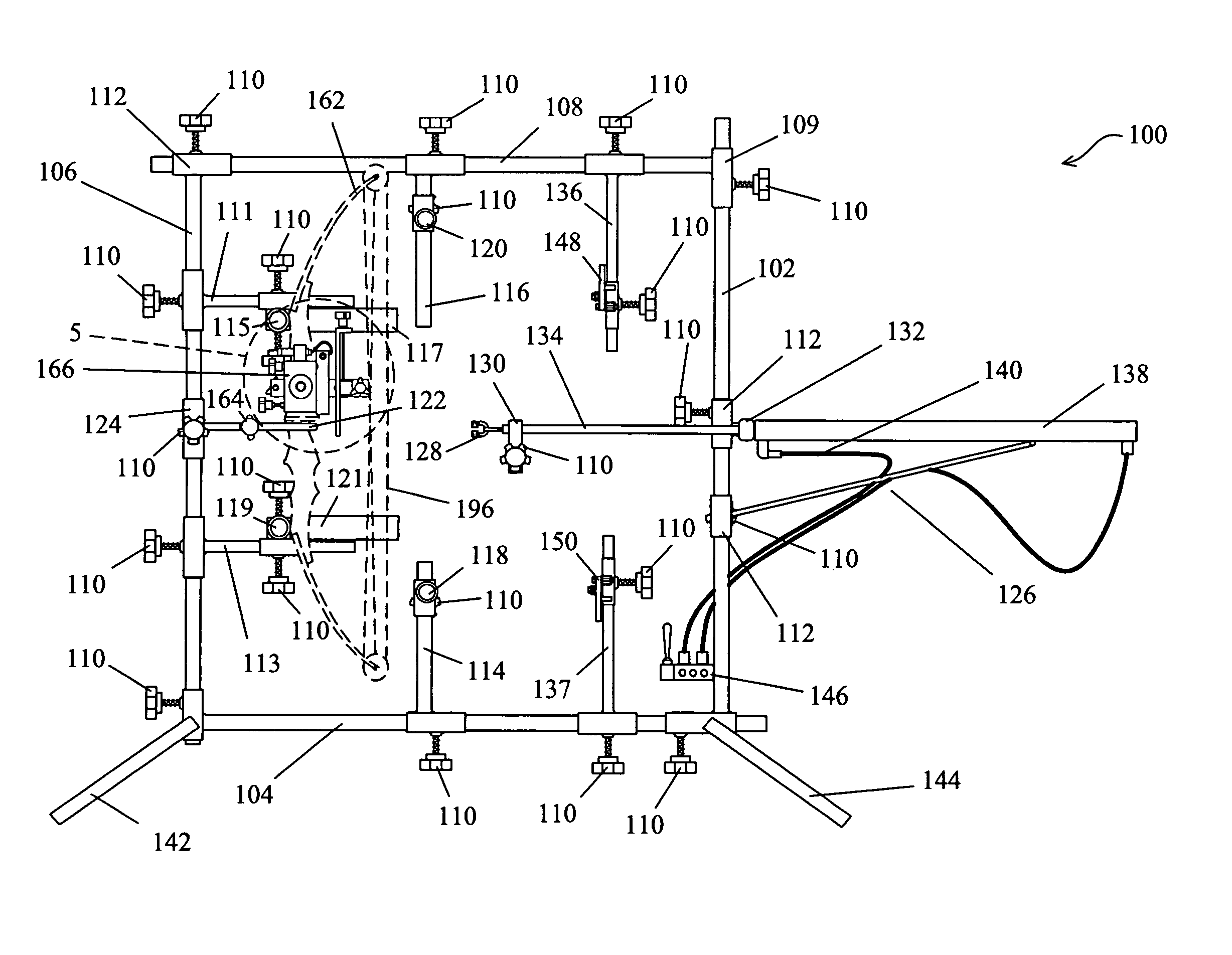
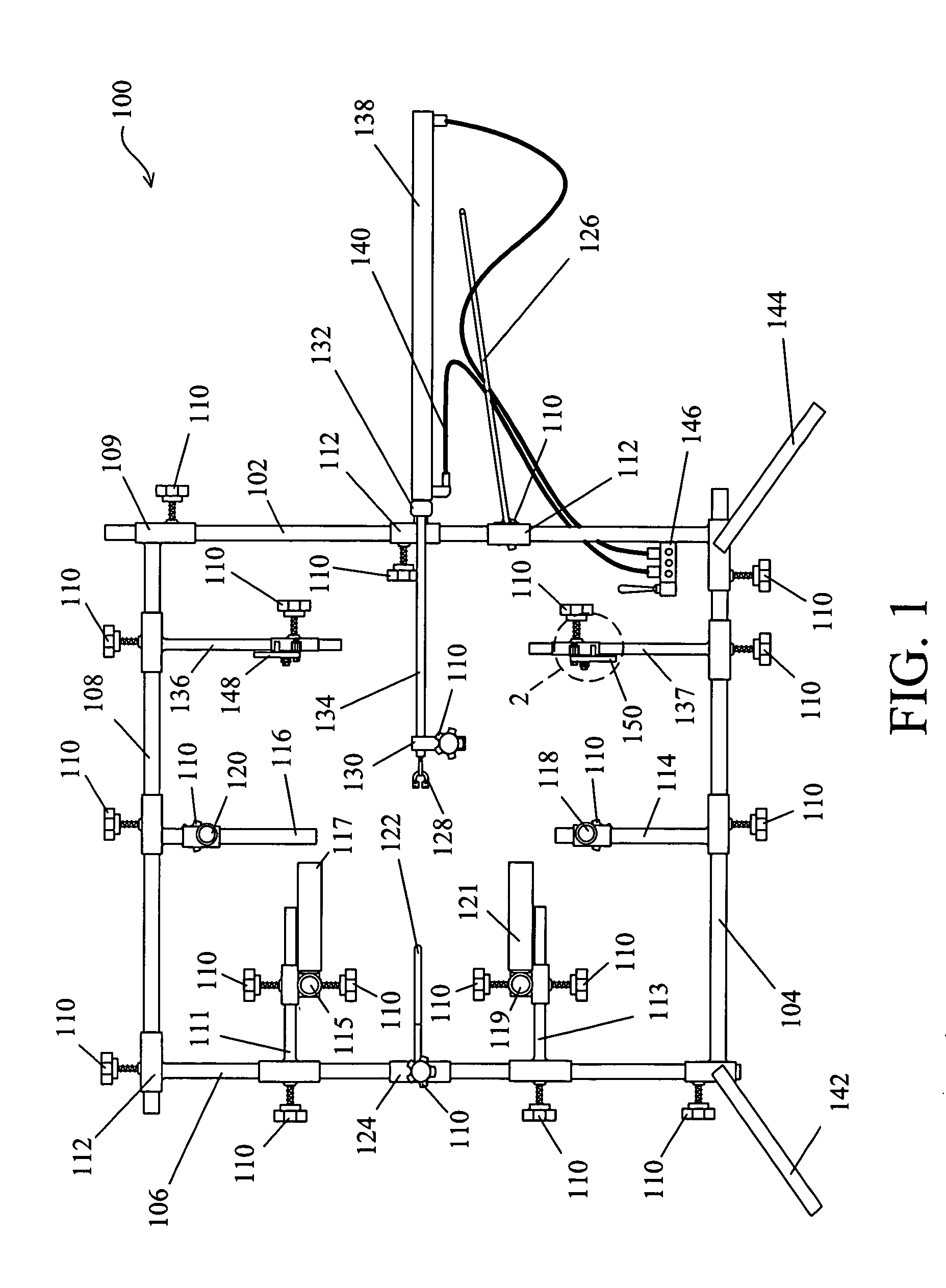
[0031]Referring to FIG. 1, a bow alignment, analysis and repair frame 100 is shown having a first vertical frame support 106 and a second vertical frame support 102. An upper horizontal frame support 108 and lower horizontal frame support 104 are provided to complete frame 100. A first leg portion 142 includes a clamping knob 110 to provide adjustability by allowing first vertical frame support 106 to selectively move up or down as needed to match a particular bow being aligned (not shown). A second leg portion 144 is allowed to move along lower horizontal frame support...


PUM


Abstract

A dynamic bow alignment, analysis and repair apparatus and system comprises an adjustable frame allowing the frame to adjust to fit any size bow. An air ram is used to controllably draw the shooting string as needed. A reference laser alignment module is mounted to a bow riser and allows a user to consistently and reliably align any bow for optimum performance based on the particularities of the selected bow subject to wear, defects and design constraints. The system removes the guesswork and allows a user to optimize any bow. A laser equipped arrow works in conjunction with the alignment module to allow the user to correctly position the shooting rest and nock indexer, and expose all functional anomalies. The system allows a user to completely quantify the performance parameters of bow performance including speed and spine tests. The system serves all major alignments and repairs.

Description

RELATED APPLICATIONS[0001]This application claims priority and herein incorporates by reference U.S. provisional patent application 60 / 973,271, filed Sep. 18, 2007.BACKGROUND OF THE INVENTION[0002]Since humans lack claws, beaks, fangs or great strength, we have had to develop weapons for survival. In the beginning, rocks and sticks served to provide a lethal edge, but humans soon began to refine these weapons by forming spears from the sticks and placing the rocks in a sling. Most experts agree that the invention of the bow and arrow was one of the most significant inventions of the human race and enabled humans to survive and dominate their environment. Archeological evidence shows the bow and arrow came into use in the early Neolithic era between 7,000 to 9,000 years ago, and possibly earlier in some regions, and was the weapon of choice for hunting until the advent of firearms. Today, the tradition continues by sportsman all over the world.[0003]From the earliest times, accuracy ...

Claims


Application Information

Patent Timeline
Patent Type & Authority Patents(United States)
IPC IPC(8): G01B1/00
CPCF41B5/14F41B5/1449F41B5/1469F41B5/148
Inventor STAGG, WESLEY
Owner STAGG WESLEY
Why Eureka
Try Eureka