
Elevator system for transmitting information to passenger

a technology of elevator system and passenger, which is applied in the direction of elevator, satellite communication transmission, instruments, etc., can solve the problems of reducing the convenience of passengers, requiring extra space, and reducing the cost of instruments, so as to achieve enhanced convenience for passengers

Inactive Publication Date: 2012-01-17
TOSHIBA ELEVATOR KK
View PDF21 Cites 28 Cited by
  • Summary
  • Abstract
  • Description
  • Claims
  • Application Information

AI Technical Summary

Benefits of technology

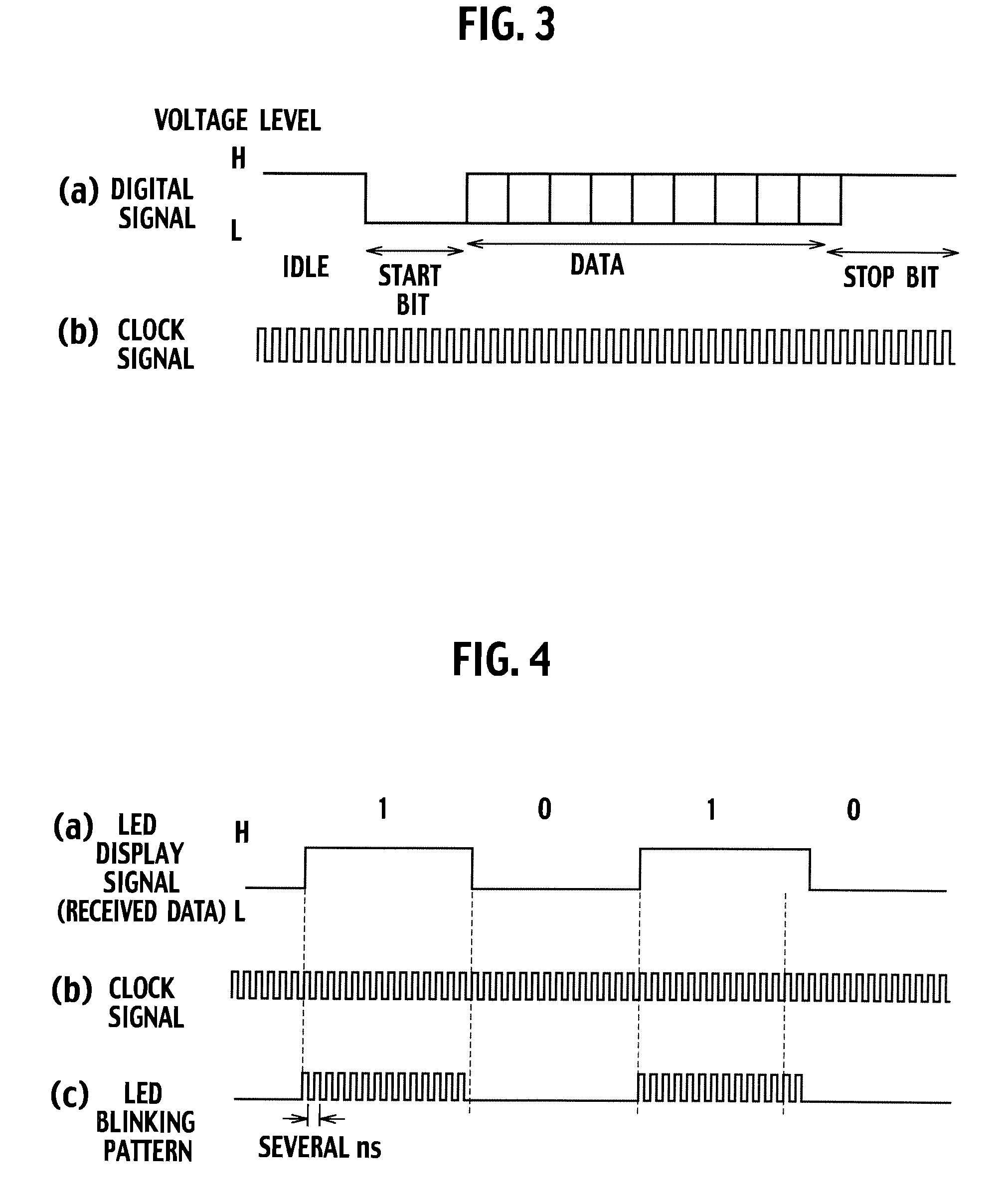
The present invention provides an elevator system that can offer various kinds of audio and video information to passengers without adding dedicated communication instruments or affecting human bodies. The system includes a data receiving unit, a pulse modulation unit, and an LED drive unit. The data receiving unit receives service state data from the elevator control device and separates it into first and second information. The second information is then used to pulse-modulate the first information and create an LED blinking pattern. The LED drive unit then drives a visible light LED placed in the elevator cage or on the platform in response to the LED blinking pattern. This elevator system offers special guide information such as a registration state of a wheelchair platform, the full-loaded state, a controlled operation state, a halt state, an under-inspection state, and a cage arrival forecast without adding dedicated communication instruments or adversely affecting human bodies. The convenience for passengers is greatly enhanced.

Problems solved by technology

However, in order to respond to such a demand, information instruments such as an announcement devices and monitor devices must be placed in the cage and on the platforms, and there has been a problem that cost for the instruments, cost for attaching / wiring work thereof, and the like are required.
Moreover, in the elevator in recent years, elimination of an extra space has progressed, and it has been sometimes difficult to attach the instruments to the elevator depending on sizes thereof.
However, in such wireless communication means as described above, there has been a problem that it is necessary to place dedicated communication instrument and transmission line in the elevator.

Method used


Image

  • Elevator system for transmitting information to passenger
  • Elevator system for transmitting information to passenger
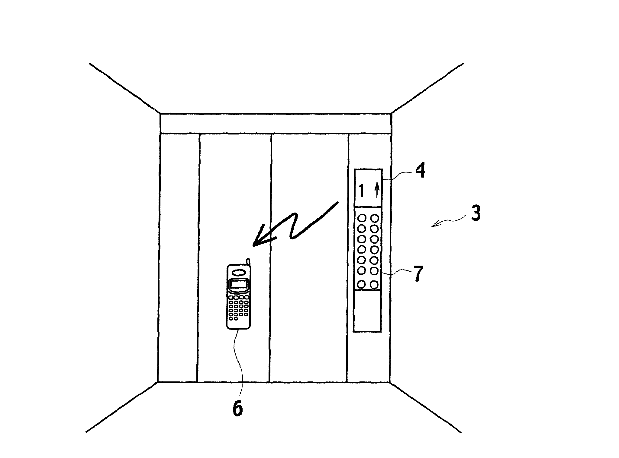
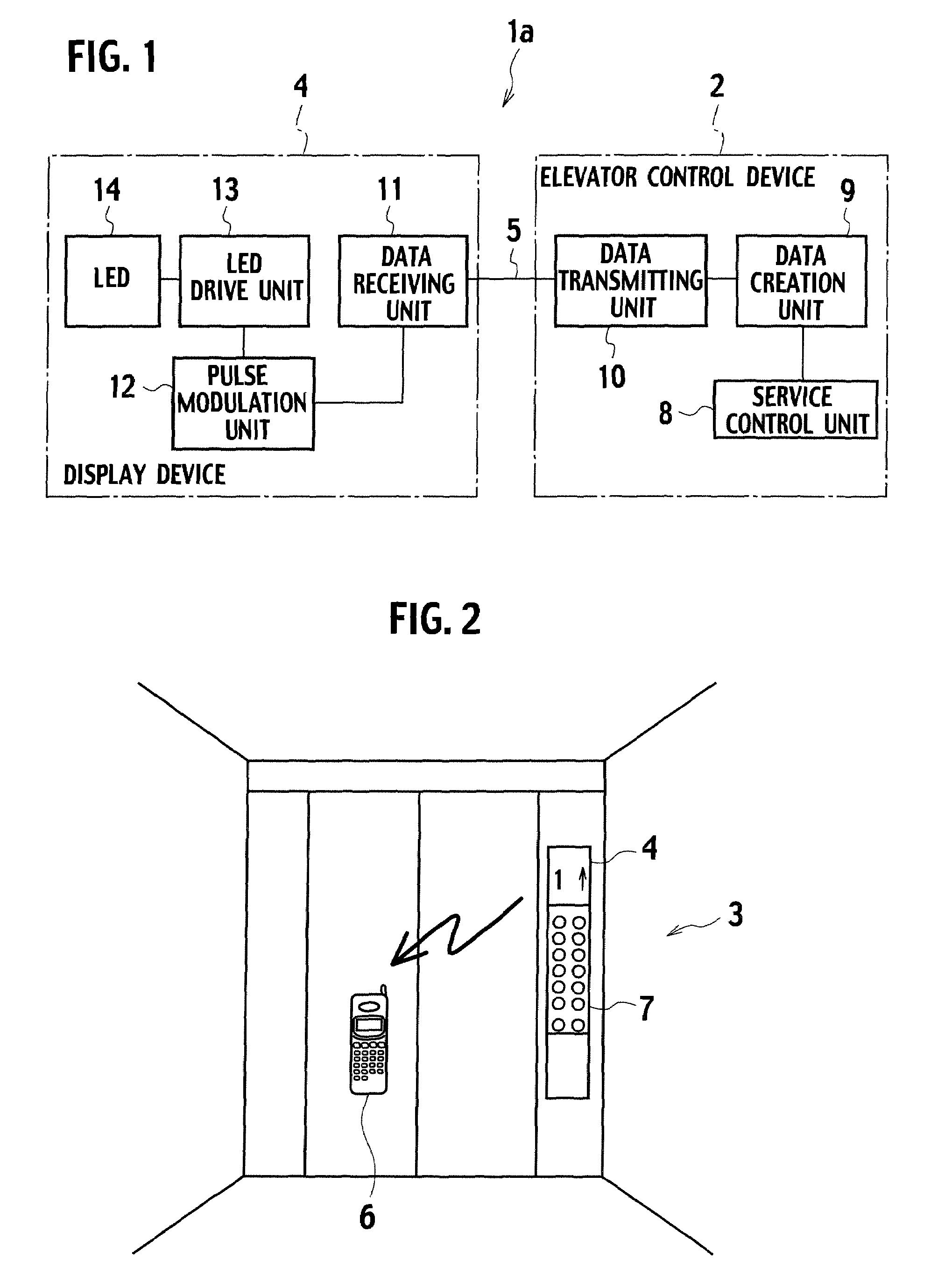
  • Elevator system for transmitting information to passenger

Examples


first embodiment

[0025]FIG. 1 is a block diagram showing a first embodiment of an elevator system according to the present invention.

[0026]An elevator system 1a shown in this drawing includes: an elevator control device 2 that controls entire operations of an elevator; a display device 4 placed in a cage 3 and the like as shown in FIG. 2; and a transmission line 5 that is composed of shielded metal twisted cable or coaxial cable, an optical cable or the like, and transfers information therethrough between the elevator control device 2 and the display device 4.

[0027]Then, based on a signal of an operation state, which is outputted from the elevator control device 2, pulse-modulated visible light is emitted from the display device 4, and usual guide information (first information), for example, position information of the cage 3, an operation direction of the cage 3, and a registration state of calls of platforms, and the like are displayed on the display device 4. Moreover, as shown in FIG. 2, a came...

second embodiment

[0039]FIG. 5 is a block diagram showing a second embodiment of the elevator system according to the present invention.

[0040]A different point of an elevator system 1b shown in this drawing from the elevator system 1a shown in FIG. 1 is that audio information, video information, textual information, control command information for use in other electronic instruments, and the like are captured into the elevator control device 2, and modulated LED light corresponding to these audio information, video information, textual information, command information for use in the other electronic instruments, and the like are created from the LED 14 of the display device 4.

[0041]In such a way, in the second embodiment, music, guidance of a building and the like can be vocally outputted from the cellular phone 6 carried by each of such users in the cage or on the platforms, or the video information and the textual information can be displayed on the display of the cellular phone. Alternatively, the...

third embodiment

[0042]FIG. 6 is a block diagram showing a third embodiment of the elevator system according to the present invention.

[0043]A different point of an elevator system 1c shown in this drawing from the elevator system 1a shown in FIG. 1 is that the transmission line 5 composed of shielded metal twisted cable or coaxial cable, an optical cable or the like is removed from between the elevator control device 2 and the display device 4. Then, a communication between the elevator control device 2 and the display device 4 is adapted to be performed by power line communication (PLC) using power lines 15 and 16 which supply electric power thereto, respectively.

[0044]In such a way, in the third embodiment, the digital signal created by the elevator control device 2 is supplied to the display device 4 by using the power line communication using the power lines 15 and 16 which supply the electric power to the elevator control device 2 and the display device 4, respectively. Accordingly, such dedica...


PUM


Abstract

An elevator system has a data receiving unit that receives service state data transmitted from a control device of an elevator. A pulse modulation unit separates the service state data received by the data receiving unit into first information data and second information data, pulse-modulates the first information data by using the second information data, and creates an LED blinking pattern. An LED drive unit drives a visible light LED placed in a cage of the elevator or on a platform of the elevator in response to the LED blinking pattern created by the pulse modulation unit.

Description

TECHNICAL FIELD[0001]The present invention relates to an elevator system, and particularly relates to an elevator system that transmits special information to passengers by using a display device or illumination device of an elevator.BACKGROUND ART[0002]In an elevator cage and on elevator platforms, a conventional elevator system places a variety of display devices (for example, a display device displaying a cage position and operation direction of an elevator and a registration state of calls of the platforms concerned by symbols such as “↑, ↓”, a display device displaying an operation state of a special operation (referred to as a controlled operation) performed by the elevator in the case of emergency such as an earthquake, a fire and a power failure, a full-loaded state of the cage, and the like, an arrival lamp (also referred to as a lantern) displaying that the elevator is approaching, an inspection lamp indicating that the elevator is under inspection, a halt lamp indicating ...

Claims


Application Information

Patent Timeline
Patent Type & Authority Patents(United States)
IPC IPC(8): B66B1/34B66B3/00H04B3/54H04B10/11H04B10/112H04B10/118H04B10/524
CPCB66B3/00B66B3/006
Inventor NAKAMURA, KUNIKO
Owner TOSHIBA ELEVATOR KK
Learn More