Motion restoring intervertebral device

a technology of intervertebral devices and motion restoration, which is applied in the field of intervertebral devices to achieve the effects of reducing stress shielding, less stiffness, and enhancing the life of the prosthesis

Active Publication Date: 2012-01-17
SEASPINE
View PDF56 Cites 76 Cited by
  • Summary
  • Abstract
  • Description
  • Claims
  • Application Information

AI Technical Summary

Benefits of technology

[0006]In a broad sense a motion restoring prosthesis adapted to be placed between the ends of two bones adjoining a mammalian appendage or spinal joint, in accordance with the present invention, includes two components with each component defining an outer surface for attachment to a respective bone end and an articulating surface for engaging the articulating surface of the other component. At least one of the components has an inner and outer section. The inner section, defining the articulating surface, is made of a primary relatively hard / stiff material such as ceramic, cobalt chromium, or other hard, stiff bio-compatible material for inhibiting the wear between the articulating surfaces. The outer section is made of a secondary material (sometimes hereinafter referred to as the “bone buttressing material”) that is softer and less stiff than the primary material (sometimes referred to as the “articulating material”). Preferably the secondary material is formed of a biocompatible polymer having a hardness / stiffness characteristic closer to that of the bone to be buttressed. Polyetheretherketone (“PEEK”) or carbon fiber reinforced PEEK (“CFRPEEK”) are clear choices. These polymers reduce stress shielding by more evenly distributing the forces or load from the articulating surfaces to the respective bone interface end thereby enhance the life of the prosthesis.

Problems solved by technology

Both the Yuichiro and Gill et al. patents describe devices which rely on point contact, a potential source of excessive wear debris.
As a result any translation away from the center in the one plane will produce device and joint distraction thereby providing a self-governing resistance to limit excessive translation.

Method used


Image

  • Motion restoring intervertebral device
  • Motion restoring intervertebral device
  • Motion restoring intervertebral device

Examples


Embodiment Construction

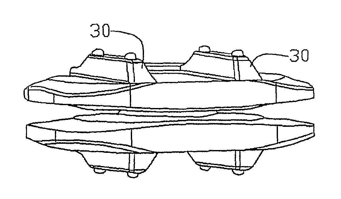
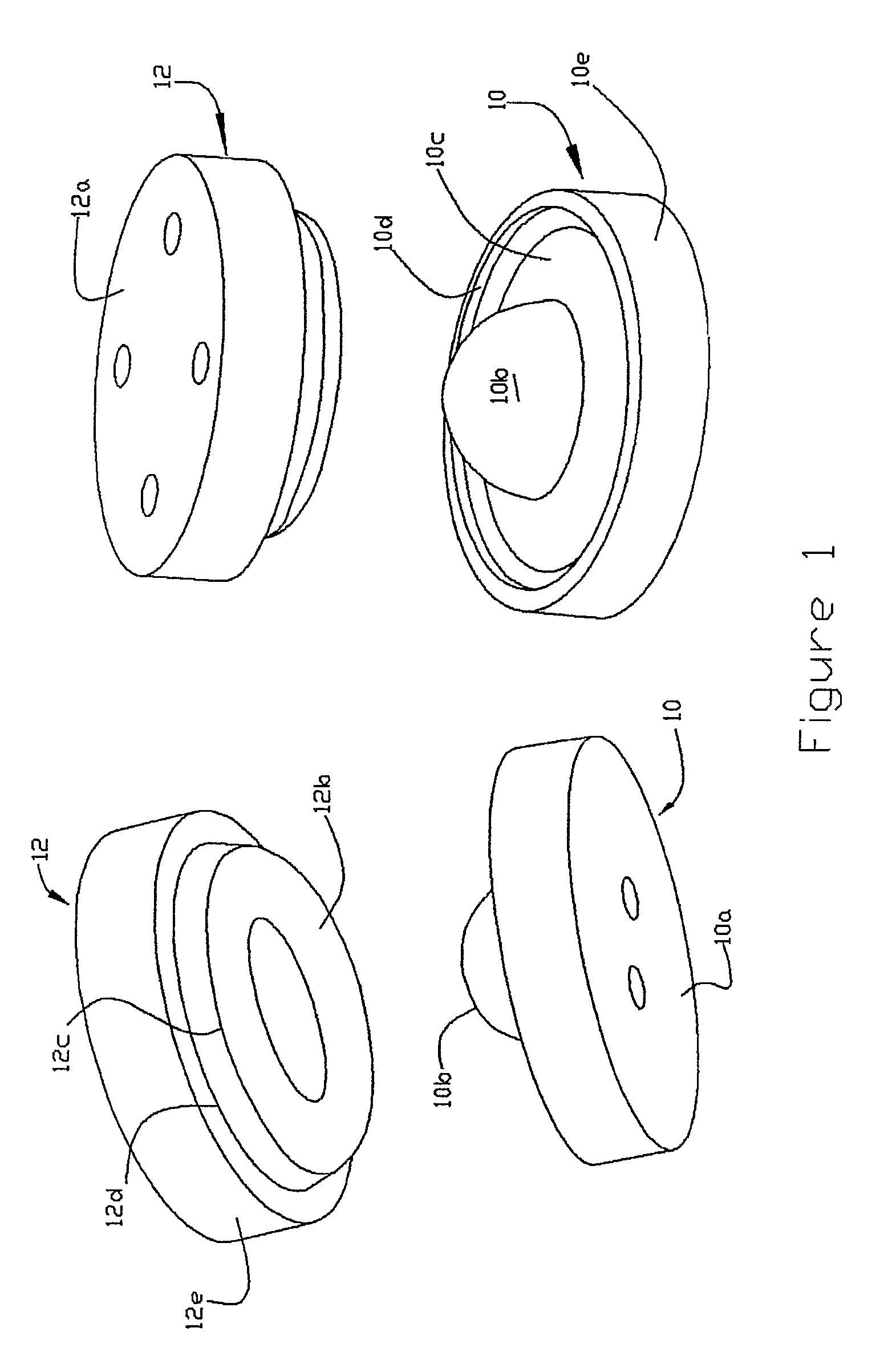
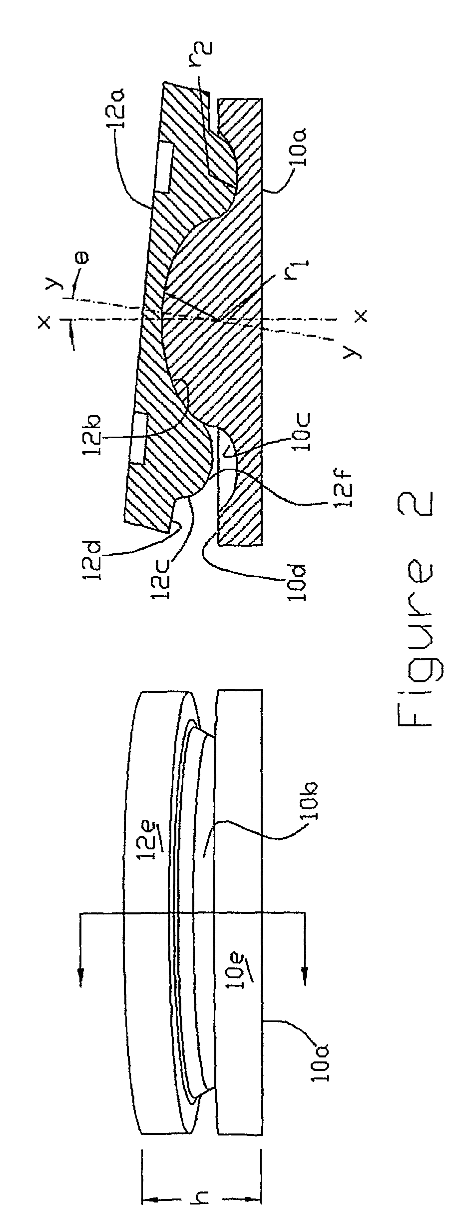
[0030]Referring now to FIGS. 1 and 2, a motion restoring intervertebral device comprises first and second components 10 and 12 with component 10 having a vertebral engaging surface 10a for buttressing against a vertebral body and an articulating surface in the form of a dome, e.g., generally semispherical convex center section 10b joined to or merged with an encircling revolved concave recess, e.g., a generally semi-cylindrical concave end section 10c which terminates in an outer lip or rim 10d. Component 12 has a vertebral engaging surface 12a for buttressing against an opposing vertebral body and a mating / articulating surface in the form of a generally semispherical concave center section 12b joined to an encircling end section 12c, having a generally semi-cylindrical convex cross-section, terminating in an outer lip or rim 12d. A peripheral wall 10e and 12e extends between the two surfaces of components 10 and 12, respectively. The radius r2 of the center sections (10b, 12b) is w...


PUM

PropertyMeasurementUnit
thicknessaaaaaaaaaa
radius r2aaaaaaaaaa
radius r2aaaaaaaaaa

Abstract

A motion restoring intervertebral device includes first and second articulating components positioned between adjacent vertebrae with the articulating surface of the first component being formed by a circular domed convex projection having a first radius. The articulating surface of the second component is formed by a generally concave recess having the first radius in the medial-lateral direction and a second larger sweeping radius in the interior-posterior direction so that the components are capable of rotating against each other in all directions and translate against each other in the anterior-posterior direction, whereby translation away from the center of the first radius will produce device and joint distraction to limit excessive translation.

Description

RELATED APPLICATION[0001]This application is based on and claims priority of U.S. Provisional Application No. 60 / 676,744 (“744 application”) for a Motion Restoring Intervertebral Device filed on May 2, 2005, the contents of the provisional application are incorporated herein by reference.FIELD OF THE INVENTION[0002]This application relates to intervertebral devices to partially or completely replace a natural spinal disc.BACKGROUND OF THE INVENTION[0003]Endeavors to treat low back pain by means of a motion restoring intervertebral element have existed for many decades. Hoffmann-Daimler disclosed many such inventions in the Germany patent 2,263,842. These included ball and socket prostheses with single and / or dual articulations and with and without motion dampening elements. The clinical use of the device containing a ball supported by two opposing sockets extending from generally flat plates, was discussed in Hoffmann-Daimler's 1974 article published in Intervertebral Disk Displacem...

Claims


Application Information

Patent Timeline
Patent Type & Authority Patents(United States)
IPC IPC(8): A61F2/44
CPCA61F2/4425A61F2/30767A61F2/3094A61F2/30965A61F2002/30014A61F2002/30016A61F2002/3065A61F2002/30654A61F2002/30841A61F2002/30892A61F2002/30906A61F2250/0018A61F2250/0019A61F2310/00029A61F2310/00179A61F2310/00203A61F2310/00407A61F2310/00796
Inventor CORDARO, NICHOLAS M.SMITH, COLIN M.
Owner SEASPINE
Why Eureka
Try Eureka