Rack for containers
a technology for containers and racks, applied in the field of racks for holding water bottles, can solve the problems of relative movement, leaking containers, and leaking containers, and achieve the effect of reducing the damage of bottles during transportation and preventing movement and vibration
- Summary
- Abstract
- Description
- Claims
- Application Information
AI Technical Summary
Benefits of technology
Problems solved by technology
Method used
Image
Examples
first embodiment
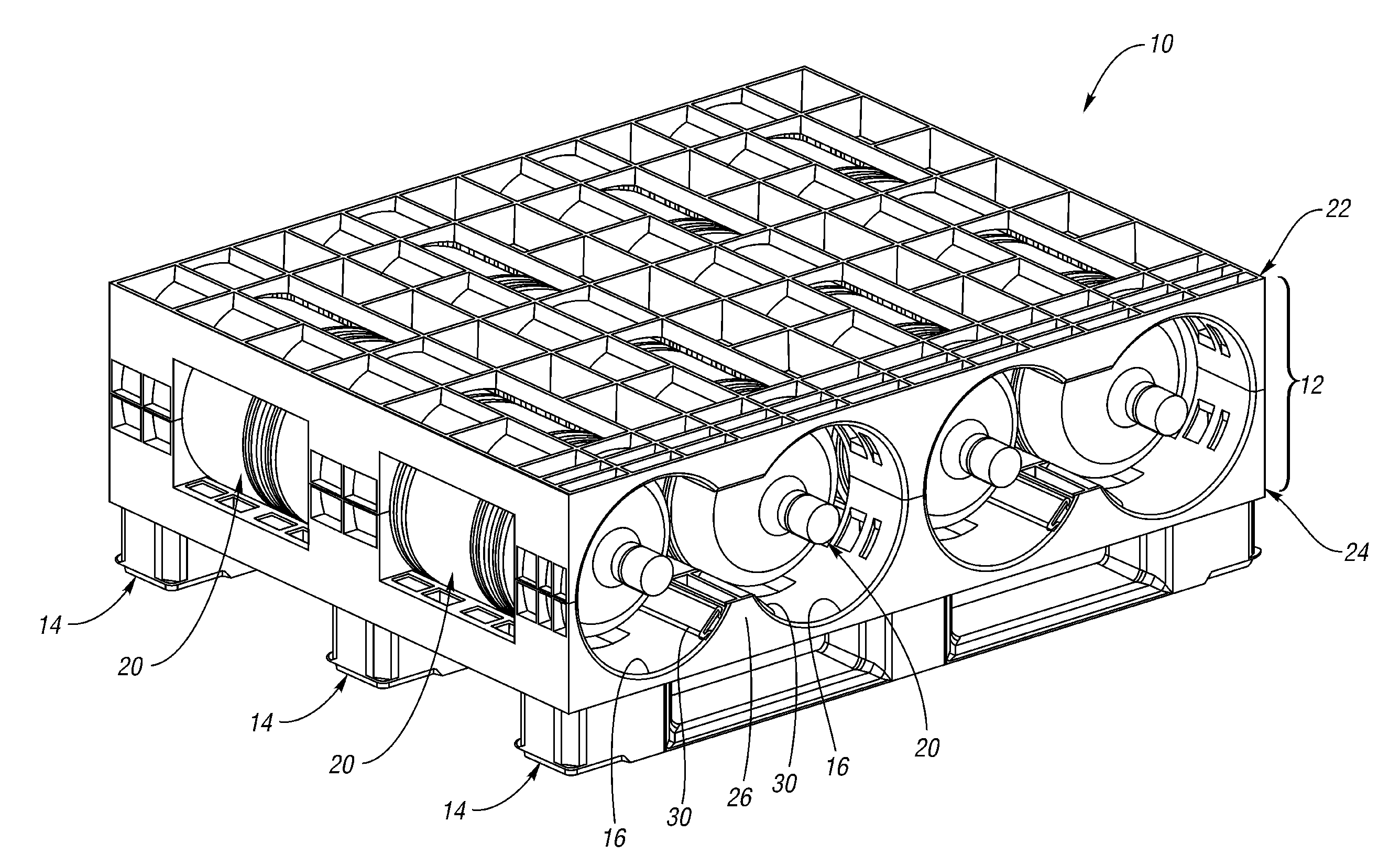
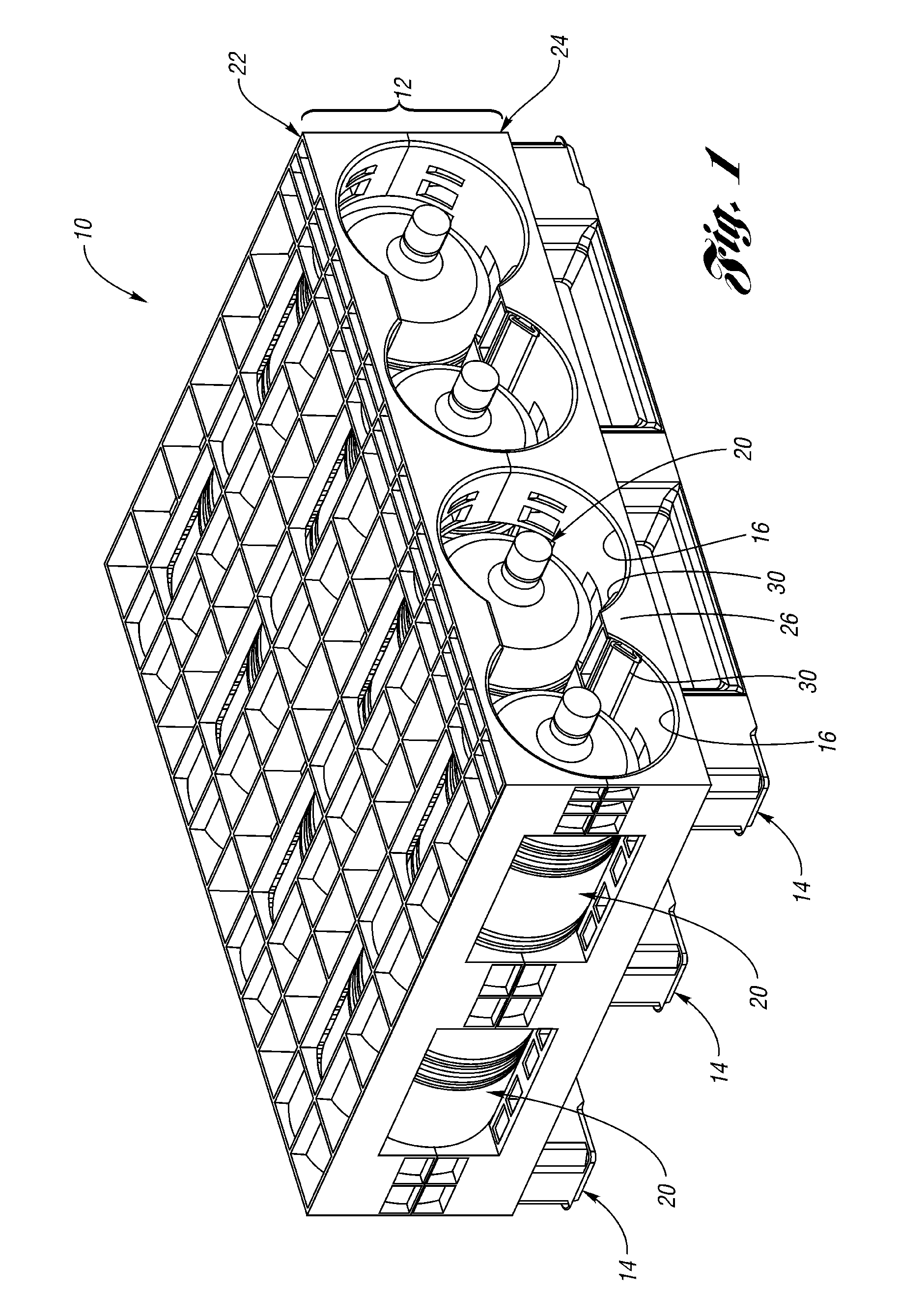
[0037]A rack 10 according to the present invention is shown in FIG. 1. The rack 10 includes a first layer 12 (or first “shelf”) supported on a plurality of supports 14. The first layer 12 defines a plurality of generally cylindrical bays 16. A pair of containers 20, in this case a pair of five gallon water bottles 20, can be received within each bay 16. The first layer 12 includes an upper section 22 and a lower section 24. The lower section 24 includes a partial divider 26 between each adjacent pair of bays 16. An expandable, inflatable clamping chamber 30 is mounted on each side of the divider 26 adjacent the bottles 20. The expandable chambers 30 are elongated, flexible pneumatic bladders or seals that extend from the front of the rack 10 to the rear of the rack 10.
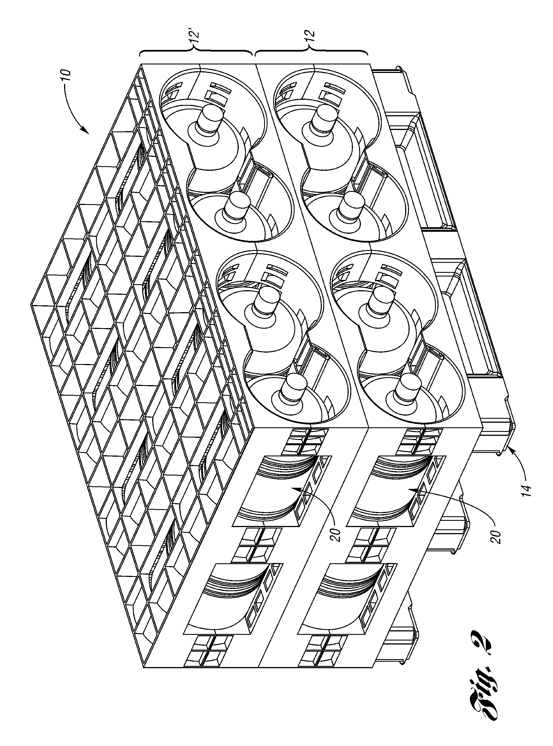
[0038]As shown in FIG. 2, the rack 10 can be expanded by adding additional shelves, such as a second layer 12′, stacked on top of the first layer 12. Both layers 12, 12′ are supported on the supports 14 above the floor...
second embodiment
[0049]A rack 110 is shown in FIG. 8. The rack 110 is similar to the rack 10 in structure and operation except as otherwise described below or shown in the drawings. Corresponding components will be designated with reference numerals prefixed with a “1.” In this rack 110, the expandable chamber 130 is positioned on top of the partial divider 126. As shown in FIG. 9, the mounting area 150 is formed on the top of the partial divider 126. FIG. 10 is a front view of the rack 110 with the expandable chambers 130 deflated. In this position the bottles 120 are not in contact with the expandable chamber 130 and can be easily inserted into or removed from the bays 116. Upon inflation of the expandable chambers 130 in the manner described above, the expandable chambers 130 each contact the bottles 20 in two adjacent bays 116 as shown in FIG. 11. This arrangement in the rack 110 reduces the total number of expandable chambers 130 that are necessary.
third embodiment
[0050]FIG. 12 illustrates a rack 210 according to a Except as otherwise described below or shown in the drawings, the rack 210 is similar in structure and operation to racks 10, 110. In this rack 210, the cylindrical bays 216 are defined on either side of the partial divider 226 and an expandable chamber 230 is provided for each bay 216. As shown in FIG. 13, the supports 214 snap-fit into the lower section 224 which in turn snap-fits into the upper section 222 for easy assembly of the rack 210.
[0051]Alternate arrangements and locations of the expandable chambers 30, 130, 230 are also possible. For example, the expandable chambers 30, 130, 230 may be placed on the upper halves 22, 122, 222 of the racks 10, 110, 210 so that the pressure exerted by the expandable chambers 30, 130, 230 is in the same direction as the gravity acting on the bottles 20. Alternatively, the expandable chambers 30, 130, 230 could be positioned inside or behind a wall of a rack section, such that expansion of...
PUM
 Abstract
Description
Claims
Application Information
 - R&D
- Intellectual Property
- Life Sciences
- Materials
- Tech Scout
- Unparalleled Data Quality
- Higher Quality Content
- 60% Fewer Hallucinations
Browse by: Latest US Patents, China's latest patents, Technical Efficacy Thesaurus, Application Domain, Technology Topic, Popular Technical Reports.
© 2025 PatSnap. All rights reserved.Legal|Privacy policy|Modern Slavery Act Transparency Statement|Sitemap|About US| Contact US: help@patsnap.com


