Paddle blade that allows use of a handle and/or paddle for any way paddling

a paddle blade and handle technology, applied in waterborne vessels, marine propulsion, vessel construction, etc., can solve the problems of inefficiency of using a single paddle blade, slow paddling speed, and inability to use a paddle handle in any way, and achieve the effect of simple and structural way, easy attachment and simple structur

a paddle blade and handle technology, applied in waterborne vessels, marine propulsion, vessel construction, etc., can solve the problems of inefficiency of using a single paddle blade, slow paddling speed, and inability to use a paddle handle in any way, and achieve the effect of simple and structural way, easy attachment and simple structur

US8100733B1Inactive Publication Date: 2012-01-24ROSS GARY +2

Image

  • Paddle blade that allows use of a handle and/or paddle for any way paddling
  • Paddle blade that allows use of a handle and/or paddle for any way paddling
  • Paddle blade that allows use of a handle and/or paddle for any way paddling

Examples


first embodiment

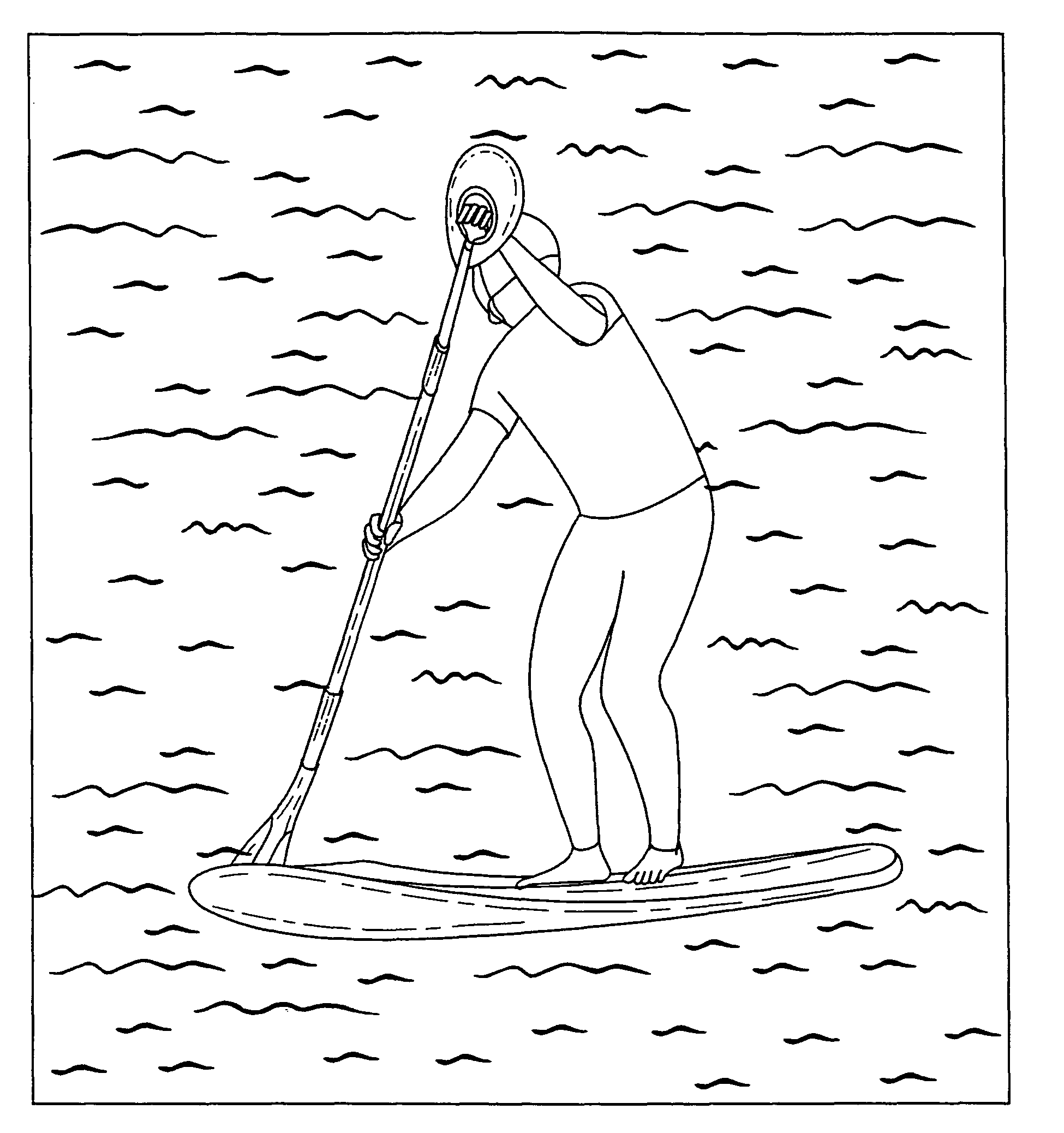
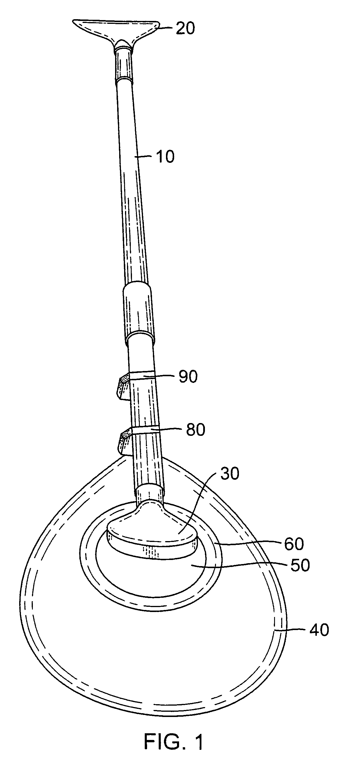
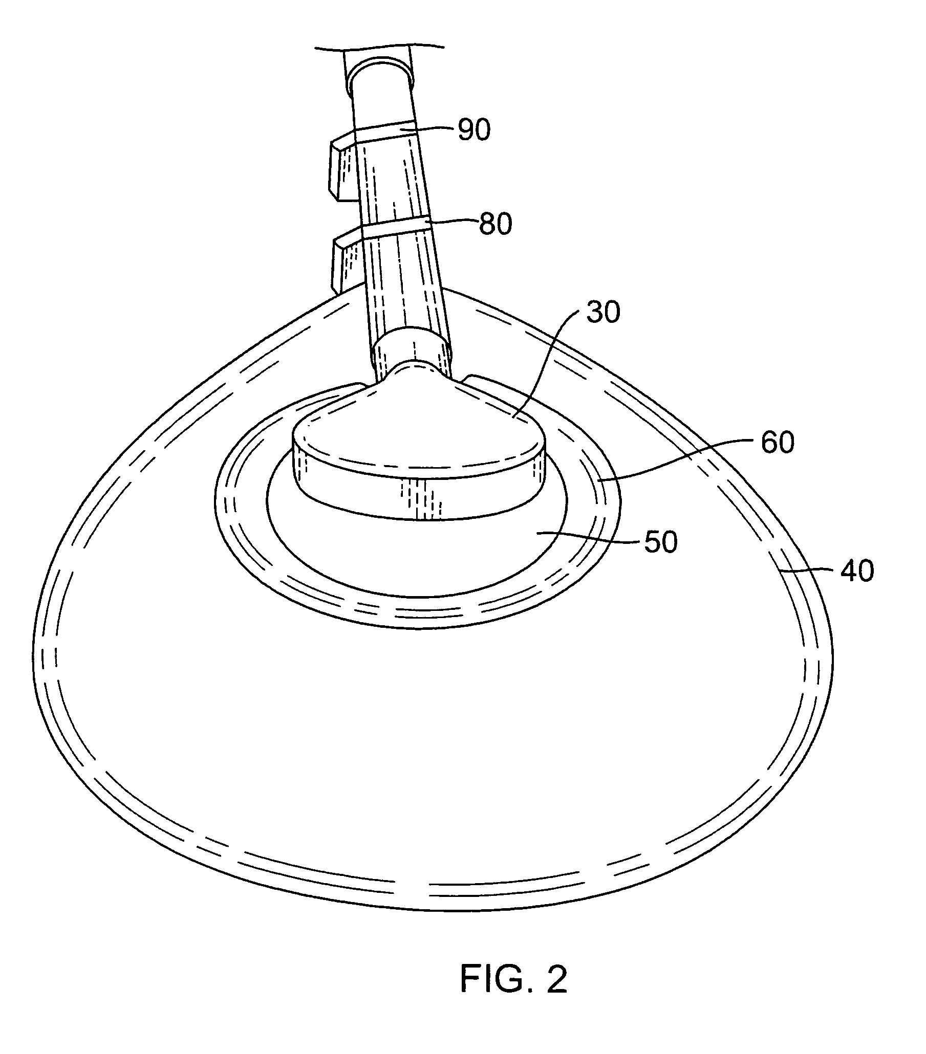
[0053]Referring to FIG. 1, there is a closeup view of one alternative embodiment of the present invention. Referring to FIG. 2, the entire embodiment is disclosed. Specifically, there is a shaft 10 and on one end of the shaft is a paddle 20 which is a conventional paddle that is typically offset from the shaft 10 at a certain angle. At the other end of the shaft 10 is a handle 30. This is typically the way a standup paddle is formed. The present invention in the first embodiment is to include a second paddle 40 with an open recess 50 and preferably a molding or barrier 60 so that there is a cushioning between a person's hand when the person grasps the handle 30 and they will not be cut by the interior of the newly added paddle 40. The paddle can be affixed to the shaft by means such as hose clamps 80 and 90. This is just one method by which the paddle can be attached to the shaft. Referring to FIG. 3, the present invention paddle 40 and its opening 50 is shown having a elongated sem...

second embodiment

[0057]The second embodiment which is shown in FIGS. 6 through 9 essentially has a shaft 110 and takes advantage of current designs of paddles 140 where the paddles 140 are offset relative to the shaft 110 by a certain angle “A” which by way of example only can be 14 degrees but it can also be in the range of 10 to 25 degrees. The present invention is to cut two slits into the paddle on either side of the elongated semi-open shaft mating member 170 into which the shaft 110 will fit and then have a mating collar 150 which also has a pair of slits 182 and 184 that respectively align with the slits 150 and 152 in the paddle and a mating section 186 which fits over the shaft 100 and then have a fastening mechanism 190 such as a velcro strap by which the paddle 140 handle is retained on the shaft 110. The paddle 140 has an interior surface 142 facing the handle 130 and an exterior surface 144. It will be appreciated that mating velcro straps are just one embodiment and a belt or any other...


PUM


Abstract

The invention is the addition to traditional shafts used for stand-up paddling that normally have a standard paddle at one end of the shaft and a handle at the other end of the shaft. The invention incorporates a second paddle attached to the shaft at the location of the handle. The paddle may have an interior opening surrounding a portion of the handle to enable a user to grasp the handle with a user's hand. Alternatively, the body of the paddle can be oriented at an angle relative to the handle so that a gap is formed between an interior surface of the body of the paddle and the handle so that the handle can be grasped by a user's hand with the user's fingers resting in the gap.

Description

BACKGROUND OF THE INVENTION[0001]1. Field of the Invention[0002]The present invention relates to the field of standup paddling where a person stands on a surfboard and holds a shaft where a paddle at one end of the shaft is inserted into the water and the person grasps the shaft by a handle at the other end of the shaft so that the paddle can be stroked into the water to move the board along.[0003]2. Description of the Prior Art[0004]Over the last few years there has been a popularization of a sport whose origin can be traced back to the 1940's in Hawaii. The new sport is called standup paddling (SUP). A large very buoyant surfboard is used so the standing surfer can paddle while the board is in flat water. A single bladed paddle with a handle is used on a long shaft with a handle or a simple “T’ at the other end. The typical blade of the single blade was discovered to work best if angled at about 14% relative to the shaft.[0005]The surfer traditionally stands up and paddles with th...

Claims


Application Information

Patent Timeline
24 Jan 2012
Publication
US8100733B1
IPC
B63H16/04; B63H16/10
CPC
B63H16/04
Inventors
ROSS, GARY; BRAGG, BILL