Tool with articulation lock

a technology of articulation lock and tool, which is applied in the direction of surgical instrument support, application, surgical forceps, etc., can solve the problems of increasing the risk of trauma to surrounding tissues, increasing patient discomfort, and increasing the risk of injury to surrounding tissues, so as to increase the tension of cables, and increase the effect of cable tension

Active Publication Date: 2012-01-24
INTUITIVE SURGICAL OPERATIONS INC
View PDF175 Cites 831 Cited by
  • Summary
  • Abstract
  • Description
  • Claims
  • Application Information

AI Technical Summary

Benefits of technology

[0013]Some embodiments have an articulation lock that includes a link friction increasing element, such that when the lock is engaged, increased friction impedes movement of the links. Increasing friction can partially impede link movement such that the link movement is malleable. Increasing friction can also fully impede link movement such that link movement is substantially blocked or prevented. Thus at the baseline level of friction that manifests on the link surfaces, the links can be considered freely moveable. With increasing levels of friction, link movement is such that the articulation mechanism as a whole is malleable, and with further increase in friction, the articulation mechanism seizes such that there is substantially no movement. With the articulation mechanism in an articulated configuration, application of friction can prevent movement of links from that articulated configuration.
[0027]The method of changing the position of the lock may be applied to a lock in a disengaged position, and wherein the changing the position comprises engaging the lock. Engaging the lock may be applied to a tool wherein the articulation mechanism comprises tension load bearing members (cables for example), connecting the links and the articulation lock comprises a tension load bearing member (cable) tension adjusting mechanism configured to increase cable tension when engaging the lock. Engaging a lock with a cable tension adjusting mechanism may be applied to an articulation mechanism when it is in either an unarticulated configuration (which can be understood as a neutral or straight configuration), or it can be applied to an articulation mechanism when it is in an articulated configuration, in which case the articulated configuration is maintained as the mechanism is locked. Engaging a lock with a cable tension adjusting mechanism may include increasing tension on cables such that movement of the articulation mechanism is partially impeded; and by having its movement partially impeded, the articulation mechanism becomes malleable. Engaging a lock with a cable tension adjusting mechanism may also include increasing tension on the cables such that movement of the articulation mechanism is substantially blocked. Exemplary embodiments of a lock including a cable tension adjusting mechanism include a threaded element for increasing tension on the cables, and a cam lever mechanism for adjusting the length of the shaft, lengthening the shaft having the effect of increasing tension on the cables.

Problems solved by technology

Oftentimes, this limited range of motion makes it difficult to negotiate acute angles (e.g., in the rectosigmoid colon), creating patient discomfort and increasing the risk of trauma to surrounding tissues.
Although there are many benefits of laparoscopic surgery, e.g., less postoperative pain, early mobilization, and decreased adhesion formation, it is often difficult to achieve optimal retraction of organs and maneuverability of conventional instruments through laparoscopic ports.
In some cases, these deficiencies may lead to increased operative time or imprecise placement of components such as staples and sutures.

Method used


Image

  • Tool with articulation lock
  • Tool with articulation lock
  • Tool with articulation lock

Examples


Embodiment Construction

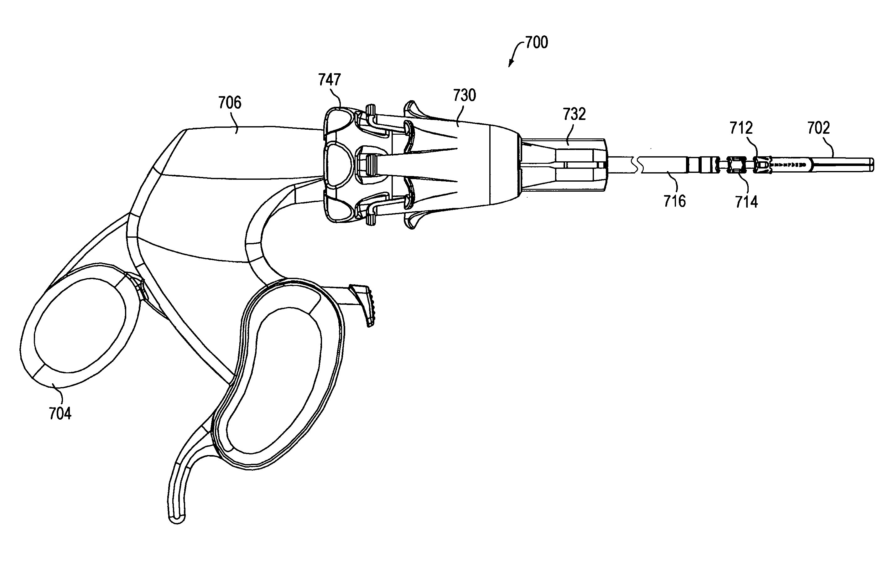
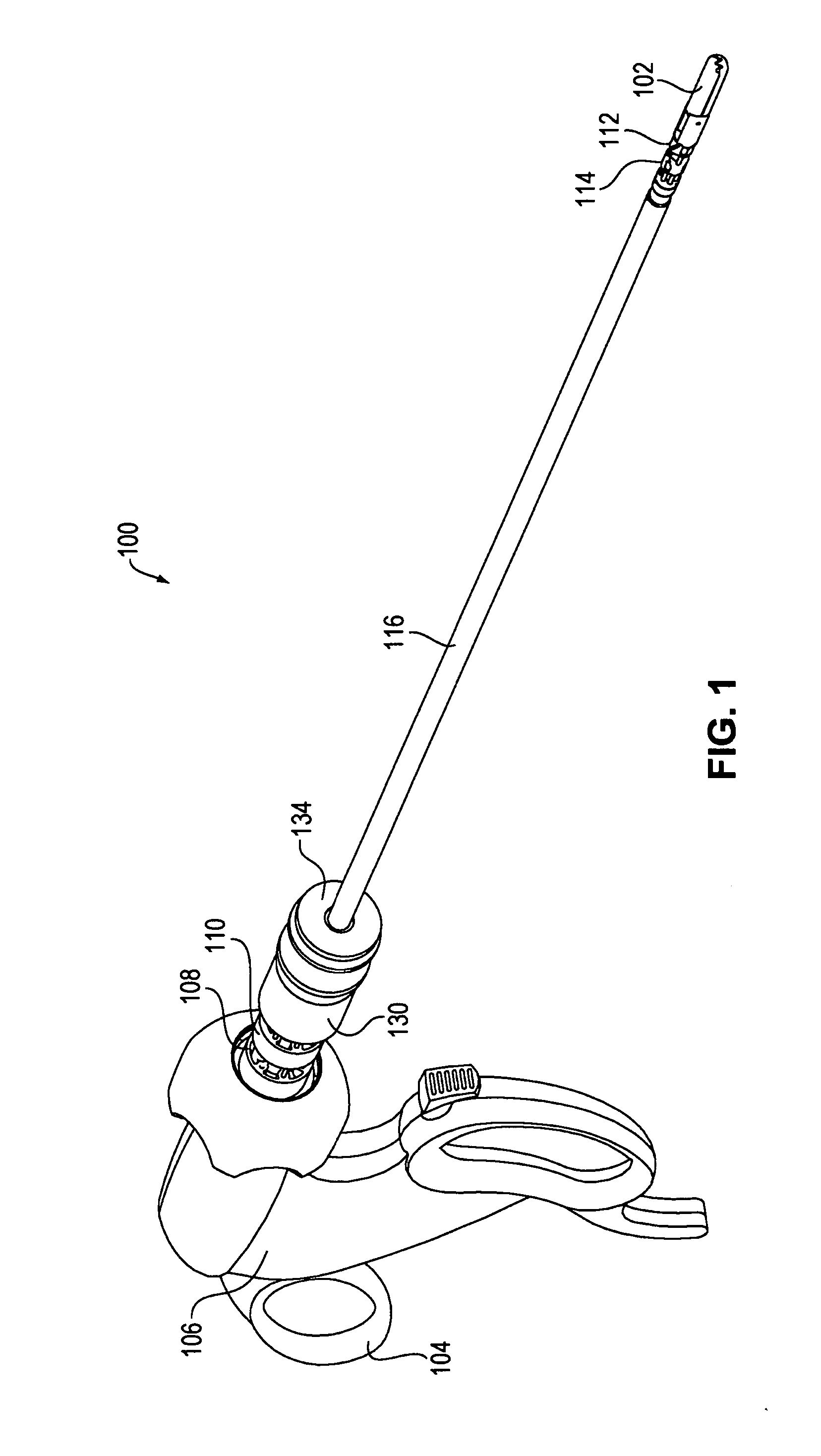
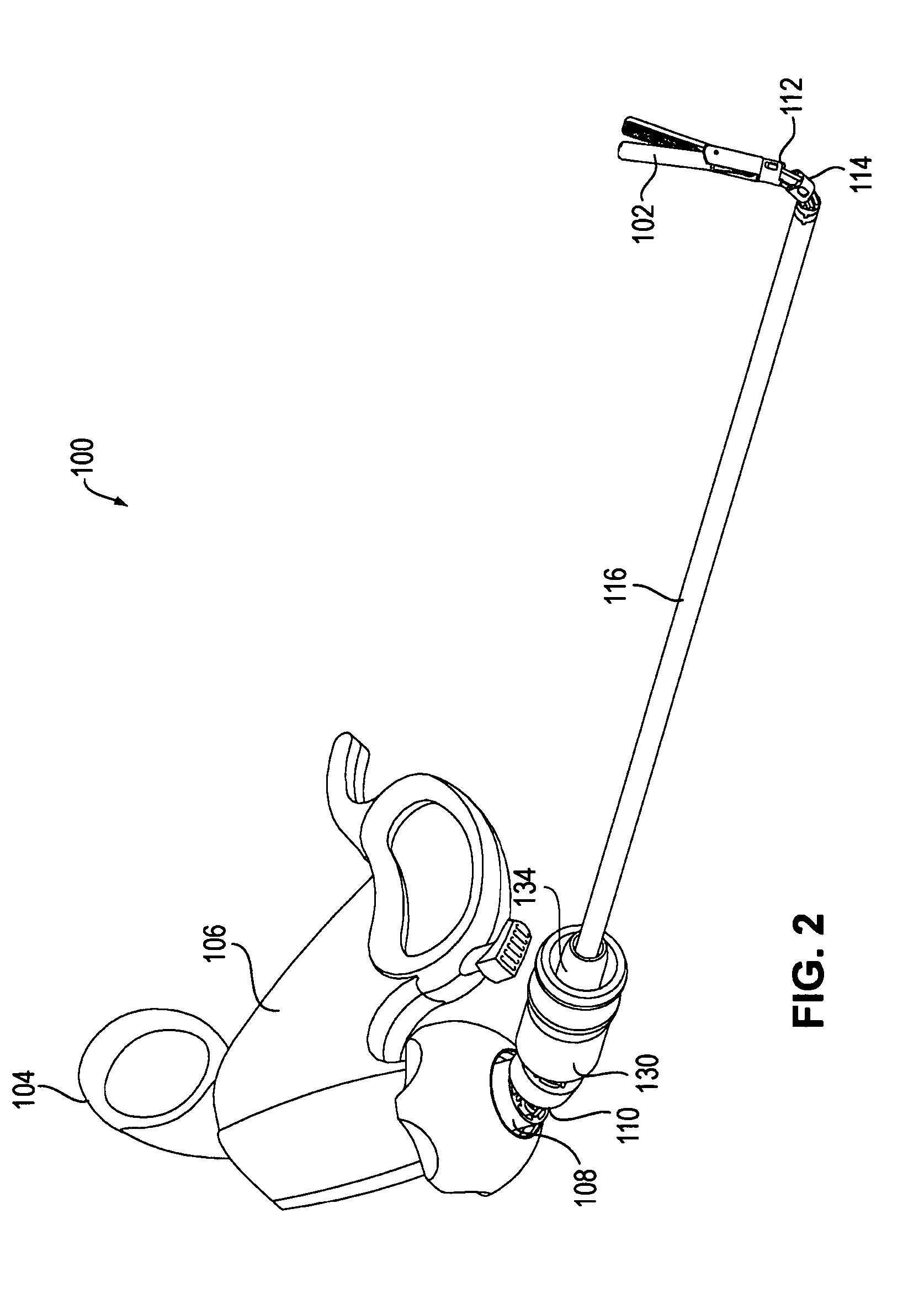
Articulating Instruments

[0079]Steerable articulating instruments are described in U.S. Pat. No. 7,090,637; US 2005 / 0107667; US 2005 / 0273084; US 2005 / 0273085; US 2006 / 0111209, and US 2006 / 0111210. The articulating mechanisms of the tools described in those publications use multiple pairs of segments or links controlled, e.g., by multiple sets of cables, as well as tools that have a single pair of links, connected by a single set of cables, such as those described in U.S. Pat. No. 5,916,146. Depending upon the specific design of the device, the links can be discrete segments (as described, e.g., in U.S. Pat. No. 7,090,637) or discrete portions of a flexible segment (as described, e.g., in US 2005 / 0173085). The instrument may also include steerable or controllable links, e.g., as described in US 2005 / 0273084, US 2006 / 0111209, and US 2006 / 0111210. Embodiments of the invention are not specific to any particular type of link, and may include any type of link known in the art.

[0080]When us...


PUM


Abstract

The invention provides surgical or diagnostic tools and associated methods that offer user control for operating remotely within regions of the body. These tools include a proximally-located actuator for the operation of a distal end effector, as well as proximally-located actuators for articulational and rotational movements of the end effector. Control mechanisms and methods refine operator control of end effector actuation and of these articulational and rotational movements. An articulation lock allows the fixing and releasing of both neutral and articulated configurations of the tool and of consequent placement of the end effector. The tool may also include other features. A multi-state ratchet for end effector actuation provides enablement-disablement options with tactile feedback. A force limiter mechanism protects the end effector and manipulated objects from the harm of potentially excessive force applied by the operator. A rotation lock provides for enablement and disablement of rotatability of the end effector.

Description

CROSS REFERENCE TO RELATED APPLICATIONS[0001]This application is a continuation in part of U.S. patent application Ser. No. 11 / 181,445 (filed Jul. 13, 2005), now U.S. Pat. No. 7,615,066 B2, which is a continuation of U.S. patent application Ser. No. 10 / 444,769 (filed May 23, 2003), now U.S. Pat. No. 7,090,637 B2, the disclosures of which are incorporated herein by reference. This application is also a continuation in part of U.S. patent application Ser. No. 11 / 121,668 (filed May 3, 2005), which claims priority to U.S. Patent Application Ser. No. 60 / 630,912 (filed Nov. 24, 2004). This application is further related to the following concurrently filed U.S. patent applications: U.S. patent application Ser. No. 11 / 787,607 (filed Apr. 16, 2007; “Tool with rotation lock” of Hinman and Danitz), U.S. patent application Ser. No. 11 / 787,599 (filed Apr. 16, 2007, “Tool with end effector force limiter” of Hinman and Bertsch), U.S. patent application Ser. No. 11 / 787,605 Filed Apr. 16, 2007, “Too...

Claims


Application Information

Patent Timeline
Patent Type & Authority Patents(United States)
IPC IPC(8): A61B1/00H04M1/724
CPCA61B1/0055A61B1/008A61B17/29A61B17/2909A61B2017/2946A61B2017/00477A61B2017/291A61B2017/2927A61B19/26A61B90/50A61B2090/508A61B2017/00314A61B2017/2929H04B7/2125A61B34/70A61B34/71A61B17/00234A61B2017/0046H04M1/724A61B17/320016A61B2017/00367A61B2017/0042H04W24/08
Inventor HEGEMAN, DAVID ELIASDANITZ, DAVID J.HINMAN, CAMERON D.ALVORD, LINCOLN J.
Owner INTUITIVE SURGICAL OPERATIONS INC
Why Eureka
Try Eureka