
Energy source isolation and protection circuit for an electronic device

a protection circuit and energy source technology, applied in the field of electronic devices, can solve the problems of battery loss, battery health and lifespan, and certain types of rechargeable batteries used in small electronic equipment,

Active Publication Date: 2012-01-24
MEDTRONIC MIMIMED INC
View PDF12 Cites 184 Cited by
  • Summary
  • Abstract
  • Description
  • Claims
  • Application Information

AI Technical Summary

Benefits of technology

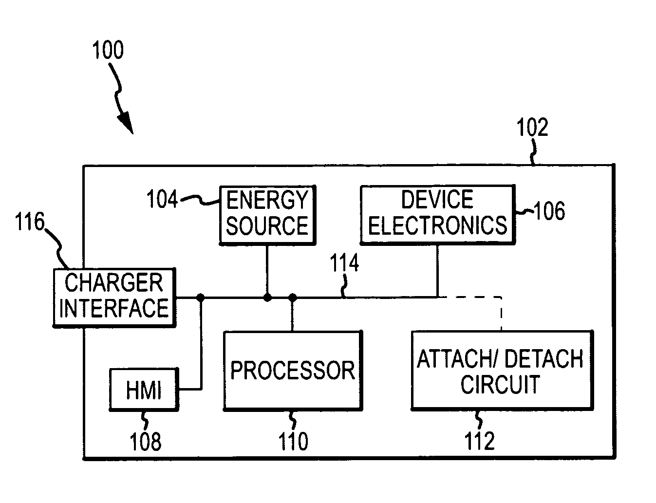
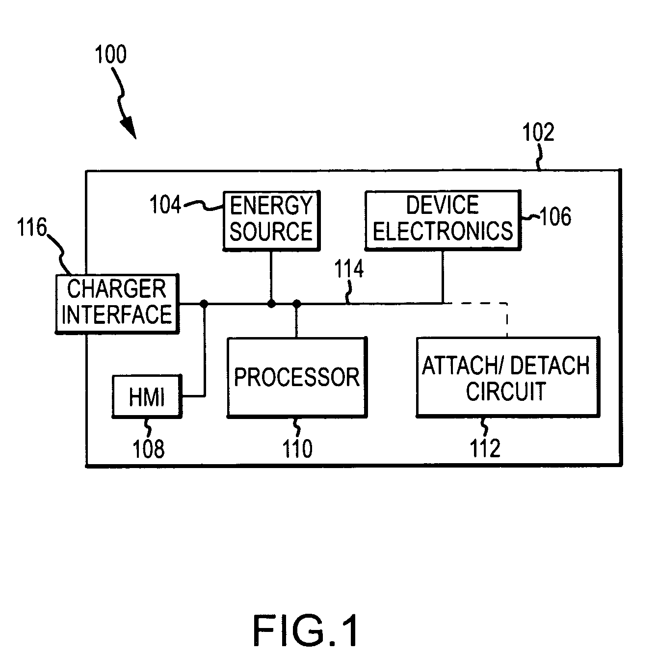
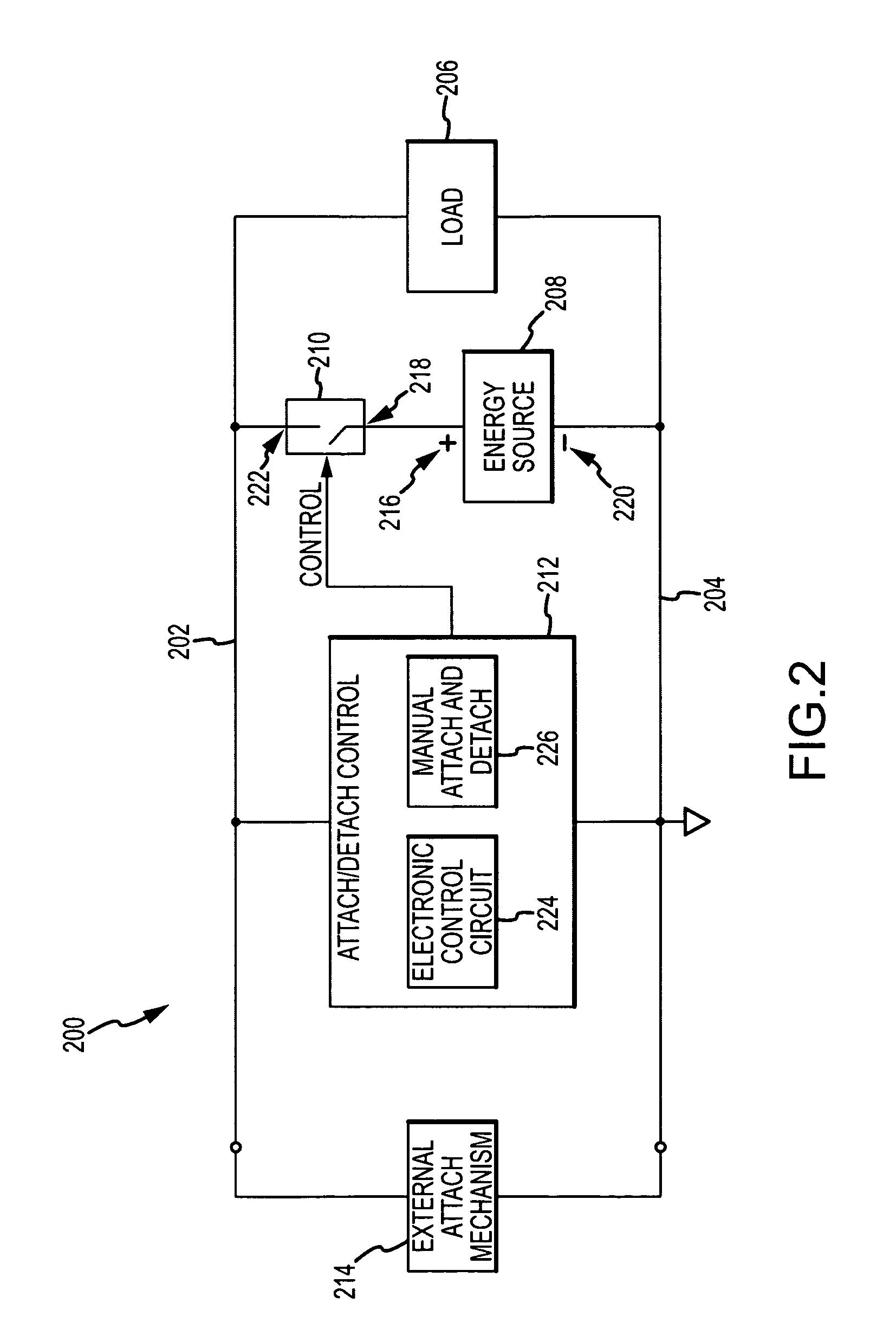
The patent describes an energy source isolation and protection circuit for electronic devices. The circuit includes a supply voltage rail, a reference voltage rail, and an energy source with a positive and negative terminal. The circuit also includes an electrically controlled switch and a control circuit. When the energy source voltage drops below a threshold voltage, the control circuit opens the electrically controlled switch to isolate the energy source from the load and remove it from the control circuit. The circuit can detect the load voltage and maintain the energy source in the isolated state until an external stimulus causes it to close. The technical effect of this circuit is to provide a safe and effective way to isolate and protect the energy source of electronic devices.

Problems solved by technology

Certain types of rechargeable batteries (e.g., lithium ion and lithium polymer batteries) used in small electronic equipment can be susceptible to damage caused by overcharging or over-discharging (i.e., an undercharge condition).
Unfortunately, conventional battery supervisory circuits remain electrically connected to the monitored battery, even after the battery has been disconnected from the primary load.
Consequently, the supervisory circuit itself can cause the battery to lose charge and voltage over time.
As a result, the health and lifespan of the battery can be negatively affected by such a supervisory circuit.

Method used


Image

  • Energy source isolation and protection circuit for an electronic device
  • Energy source isolation and protection circuit for an electronic device
  • Energy source isolation and protection circuit for an electronic device

Examples


Embodiment Construction

[0016]The following detailed description is merely illustrative in nature and is not intended to limit the embodiments of the subject matter or the application and uses of such embodiments. As used herein, the word “exemplary” means “serving as an example, instance, or illustration.” Any implementation described herein as exemplary is not necessarily to be construed as preferred or advantageous over other implementations. Furthermore, there is no intention to be bound by any expressed or implied theory presented in the preceding technical field, background, brief summary or the following detailed description.

[0017]Techniques and technologies may be described herein in terms of functional and / or logical block components, and with reference to symbolic representations of operations, processing tasks, and functions that may be performed by various components or devices. It should be appreciated that the various block components shown in the figures may be realized by any number of hard...


PUM


Abstract

An energy source isolation and protection circuit is provided for an electronic device, such as a patient-worn or patient-carried medical device. The isolation and protection circuit includes a supply voltage rail, a reference voltage rail, an electrical load coupled across the supply voltage rail and the reference voltage rail, and an energy source for supplying a voltage to the electrical load via the supply voltage rail and the reference voltage rail. The isolation and protection circuit also includes a voltage-controlled switch architecture that is configured to detach and electrically isolate the energy source from the electrical load (and from itself) in response to the voltage of the energy source falling below a threshold voltage. The voltage-controlled switch architecture is also designed to maintain the energy source in the detached and electrically isolated state in the absence of operating voltage provided by the energy source to the voltage-controlled switch architecture.

Description

TECHNICAL FIELD[0001]Embodiments of the subject matter described herein relate generally to electronic devices. More particularly, embodiments of the subject matter relate to protection circuits for energy sources such as rechargeable batteries.BACKGROUND[0002]The prior art is replete with portable electronic devices that are powered by rechargeable energy sources such as batteries. Portable consumer grade electronic devices have become ubiquitous in modern society; such devices include digital media players, mobile telephones, personal digital assistants, handheld video games, and the like. Moreover, portable electronic devices are commonly used for medical applications and systems. For example, the following types of medical devices can be implemented in a battery-powered platform: a wearable fluid infusion pump; a portable patient monitor device; a controller for a patient-worn medical device; or the like.[0003]Certain types of rechargeable batteries (e.g., lithium ion and lithiu...

Claims


Application Information

Patent Timeline
Patent Type & Authority Patents(United States)
IPC IPC(8): H02J7/00
CPCH02J7/0031H02J2007/004H02J7/00306
Inventor BISHOP, DENNIS P.SPURLIN, JON M.
Owner MEDTRONIC MIMIMED INC
Learn More