Microwave ranging sensor

a microwave and sensor technology, applied in the field of security systems, can solve the problems of pet may trigger a false alarm, inherent weaknesses of the pir detector, and the combination of detectors does not improve the detection of intruders, so as to reliably detect intruders and accurate distance measurements

Active Publication Date: 2012-01-24
ADEMCO INC
View PDF20 Cites 14 Cited by
  • Summary
  • Abstract
  • Description
  • Claims
  • Application Information

AI Technical Summary

Benefits of technology

[0011]The present invention is a method and a motion detector for detecting an intruder in a protected space that uses a MW sensor to determine an accurate distance measurement to the intruder without an ambiguity problem. The accurate distance measurement reduces the false alarms typically associated with MW motion detectors due to motion outside the protected space and vibration within the protected space. It also allows the motion detector to precisely set signal threshold levels to reliably detect an intruder while discriminating against an animal or other moving object.
[0013]The method further includes the steps of determining an amplitude for each IF signal component; selecting a signal level based on the amplitudes, which may be an average of the three amplitudes or may be the highest amplitude of the three amplitudes; reading a stored predetermined threshold that corresponds to the accurate distance measurement; and if the signal level is greater than the predetermined threshold, generating one or more warning signals signifying motion has been detected. The predetermined threshold levels are calculated from empirical data taken from studies of signals received from humans, pets and other objects. The stored thresholds are selected so that reflected signals from humans are above the threshold while reflected signals from pets and other objects are below the threshold. The significance of the present invention is that the accuracy of the distance measurement of the intruder and the comprehensiveness of the threshold table allows the threshold to be precisely selected to eliminate false alarms and to accurately transmit an alarm signal when an intruder is in the protected space.
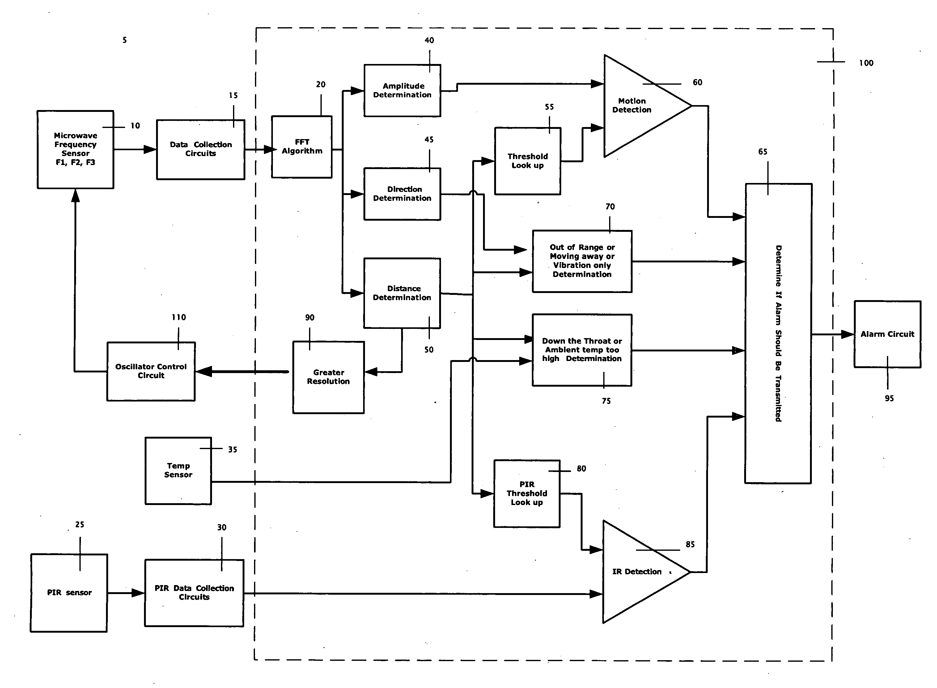
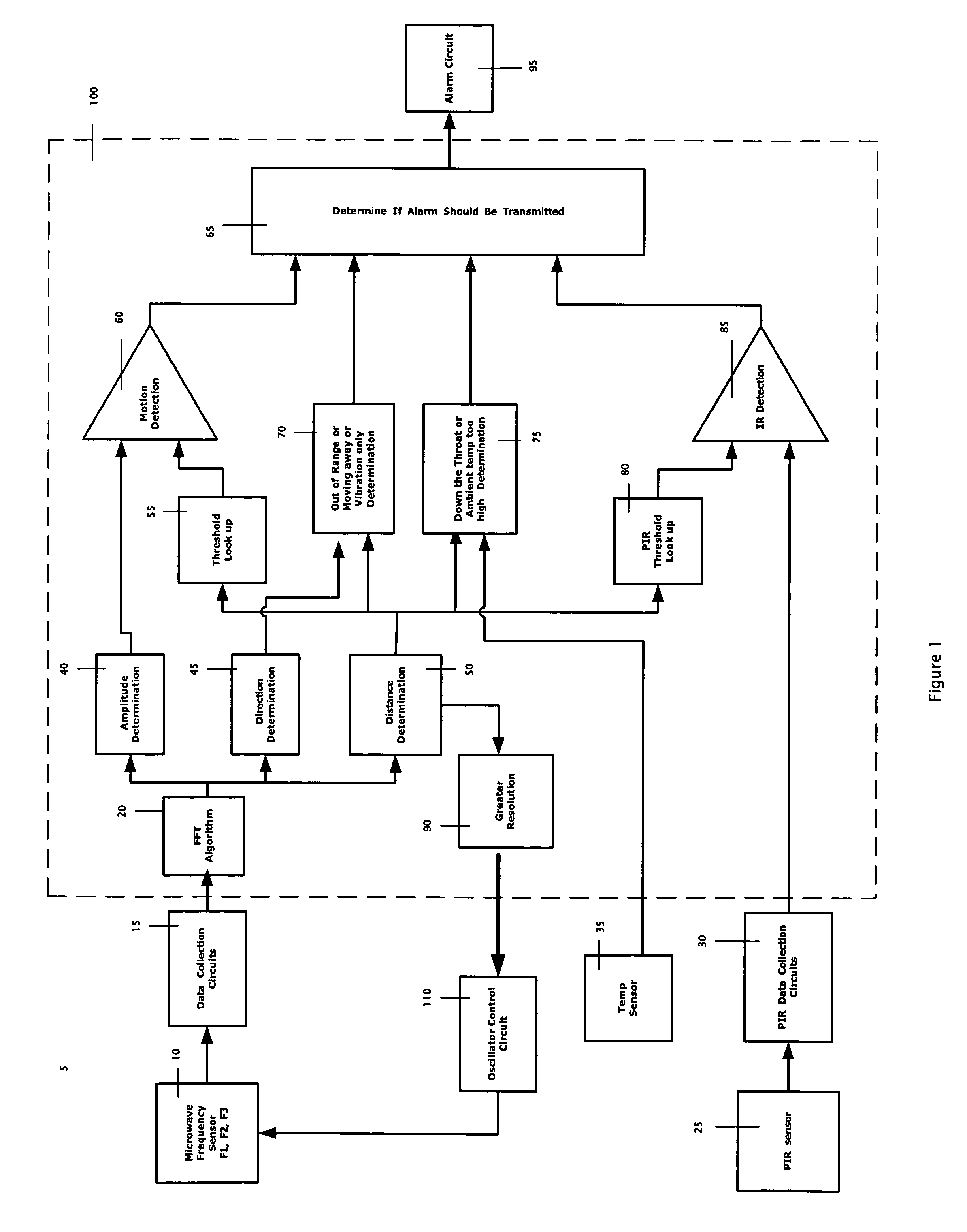
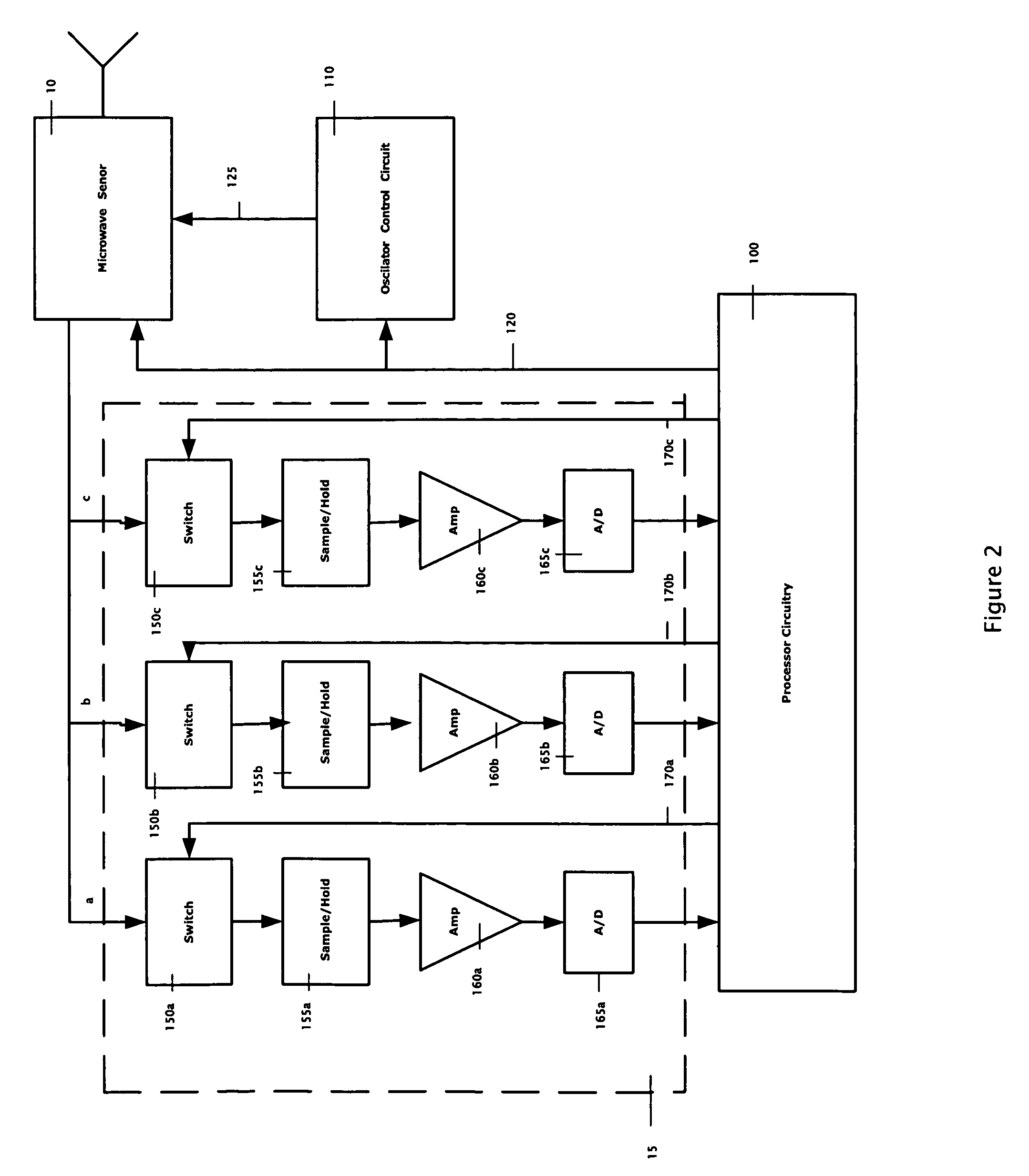
[0016]Furthermore, the microwave circuit generates the IF signal components by combining a portion of the MW signal (at the transmitted F1, F2, or F3) with the received reflected MW signal. As the IF signal components are generated they are multiplexed onto an IF signal that is operatively connected to the data collection circuits. The data collection circuits include three detection channels (one for each frequency). The channels are sequentially enabled by the processor circuitry to match the sequential transmission of the three MW signals. The three parallel detection channels allow the three MW signals to be transmitted and received at almost the same time. Each detection channel consists of a switch circuit to provide the IF signal to the detection channel when the detection channel is enabled by the processor circuitry, a sample-and-hold circuit coupled to receive the IF signal from the switch circuit, an amplifier circuit coupled to receive the sampled IF signal, and an analog-to-digital converter circuit coupled to receive the amplified sampled IF signal and supply a digital data sample of the IF signal. The processor circuitry sequentially collects a data sample for each of the three MW signals transmitted for a predetermined number of times to generate three IF data sets. Each IF data set is then processed using an FFT algorithm to produce three phase angles, and signal strength. An automatic gain control circuit (AGC) can be used instead of the amplifier circuit.
[0017]In another embodiment of the present invention, the accuracy of the intruder distance measurement may be determined with greater resolution by reiteratively evaluating collected data sets. The method may include the steps of determining if the intruder is approximately at the maximum distance, and if the intruder is not approximately at the maximum distance, selecting a new second and third frequency based on the determined accurate distance and completing the steps to determine the accurate distance measurement again with the newly selected frequencies. A greater distance resolution is achieved with each distance calculation iteration because the dynamic range of the detector must initially cover the maximum distance of the protected space to make sure an intruder anywhere in the room is detected, and once the distance of the intruder is determined to be less than the maximum distance, the detector's dynamic range only needs to cover the determined distance. As the distance gets smaller, the resolution gets better. The maximum distance of each reiteration is inverse proportional to the difference between the frequencies of the transmitted MW signals. The method of the present invention adjusts the frequency difference by holding F1 constant and changing F2 and F3 based on the distance calculated. The difference between F1 and F2 and between F1 and F3 is very small compared to F1.

Problems solved by technology

However, the combination of the detectors does not improve detection of an intruder when the intruder is cloaked, moves down the throat (directly at the detector), or is in a high ambient temperature.
These situations are inherent weaknesses of the PIR detector.
However, a pet may trigger a false alarm when it is moving at the back of the room because the PIR sensor's field of view is cone shaped and at further distances senses IR closer to the floor.
Unfortunately, the common Doppler MW motion sensors don't have the ability to measure target distance.
A less expensive method of transmitting two different frequency MW signals and determining the phase difference between the two detected Doppler signals may be used to determine the distance, however, an ambiguity arises from a phase advance / delay uncertainty between the two signals.

Method used


Image

  • Microwave ranging sensor
  • Microwave ranging sensor
  • Microwave ranging sensor

Examples


Embodiment Construction

[0023]FIG. 1 is an illustration of the components and the processes that the motion detector 5 of the present invention uses to determine whether an intruder is present in a protected space. The components are the MW sensor 10, the data collection circuits 15, the PIR sensor 25, the PIR data collection circuits 30, the oscillator control circuit 110, the temperature sensor 35, the processor circuitry 100, and the alarm circuit 95. The oscillator control circuit 110, further described below, causes the MW sensor 10 to transmit three MW signals (F1, F2, and F3) that differ only slightly so that F2=F1+Δ1 and F3=F1+Δ2, where Δ11 and Δ21. In the preferred embodiment, the frequencies of the transmitted MW signals are initially set to cover the Maximum distance (minimum frequency difference such as few MHz). The MW sensor contains a MW receiver that receives reflected MW signals from a moving object in the protected space. The protected space is nominally a 35 ft room, but may be as large ...


PUM


Abstract

A method for detecting an intruder in a protected space that uses a microwave frequency sensor to determine an accurate distance measurement to the intruder. The accurate distance measurement reduces the false alarms typically associated with microwave frequency sensors due to motion outside the protected space and vibration within the protected space. The motion detector transmits three microwave frequency signals of different frequencies in order to eliminate an ambiguity problem when determining the accurate distance measurement. The accuracy of the intruder distance measurement may be determined with greater resolution by reiteratively transmitting and evaluating microwave frequency signals of different frequencies. The motion detector of the present invention may include a PIR sensor. The accurate distance measurement allows the motion detector to precisely set signal threshold levels for the microwave frequency detector and the passive infrared detector to reliably detect an intruder while discriminating against an animal or other moving object.

Description

TECHNICAL FIELD[0001]The present invention relates to security systems, and in particular to microwave frequency motion detectors used for monitoring a protected space.BACKGROUND ART[0002]In the security field, duel technology motion detectors consisting of a Doppler microwave frequency (MW) detector and a passive infrared (PIR) detector are used to more accurately determine if an intruder has entered a protected space. The PIR detector senses infrared radiation (IR) from the intruder while the MW detector transmits a MW signal and receives a reflected MW signal from the intruder in the field. The typical operation of a dual technology motion detector is that the sensor will generate an alarm signal when the PIR detector and the MW detector both detect the intruder. The combination of the detectors eliminates the false alarm such as wall vibration while increasing the reliability. However, the combination of the detectors does not improve detection of an intruder when the intruder i...

Claims


Application Information

Patent Timeline
Patent Type & Authority Patents(United States)
IPC IPC(8): G08B13/18
CPCG01S13/38G01S13/56G01S13/26
Inventor WU, XIAODONG
Owner ADEMCO INC
Why Eureka
Try Eureka