Supercharge Your Innovation With Domain-Expert AI Agents!

Method for acquiring a digital image with a large dynamic range with a sensor of lesser dynamic range

a digital image and sensor technology, applied in the field of digital image processing, can solve the problems of increasing noise effects, limited dynamic range, and larger quantization errors, and achieve the effect of maximizing the signal-to-noise ratio (snr)

Active Publication Date: 2012-01-24
STMICROELECTRONICS SRL
View PDF13 Cites 19 Cited by
  • Summary
  • Abstract
  • Description
  • Claims
  • Application Information

AI Technical Summary

Benefits of technology

The patent describes a method for improving the dynamic range of a sensor by adjusting the integration time of single pixels based on the light incident on them. The sensor has a plurality of pixels, each with a dedicated circuit for selecting different integration times. The method allows for the capture of multiple intensity values for each pixel, which can be used to generate a high dynamic range color image. The method also includes scaling the intensity values based on the effective integration time and interpolation to reconstruct saturated, dark, or missing pixels. The resulting color image can be compressed for display on a limited dynamic range display.

Problems solved by technology

Image sensors, that integrate the electric current generated by impinging photons such as the CMOS devices, have a dynamic range that is limited by the amount of charge that may be discriminately accumulated in correspondence of the image pixels.
For a given number of bits per pixel, larger dynamic ranges imply larger quantization errors and increasingly sensitive noise effects in the histogram of intensities relative to darker portions.
A problem with this technique is that several shots (pictures) must be taken without moving the photo-camera and the depicted objects / subjects must be still.
Under these conditions all the pictures represent exactly the same scene, otherwise it would be very difficult to align them correctly.
A drawback of this method consists in that the definition of the spatial pattern of the two different integration times heavily influences the quality of the reconstructed images.
In particular, the integration time differences set for an image with a strong contrast may not be appropriate for acquiring an image of a significantly lighter contrast.
Moreover, an erroneous choice of the spatial exposition pattern could make luminous zones of the image be acquired with a too long integration time and vice versa for the dark zones.

Method used


Image

  • Method for acquiring a digital image with a large dynamic range with a sensor of lesser dynamic range
  • Method for acquiring a digital image with a large dynamic range with a sensor of lesser dynamic range
  • Method for acquiring a digital image with a large dynamic range with a sensor of lesser dynamic range

Examples


Embodiment Construction

[0056]Because of the preeminent use of the so-called Bayer pattern [See U.S. Pat. No. 3,971,065] in color image acquisition systems, reference will be made to Bayer images, though the principles that will be described hold mutatis mutandis for sensors using a different pattern for capturing color images.

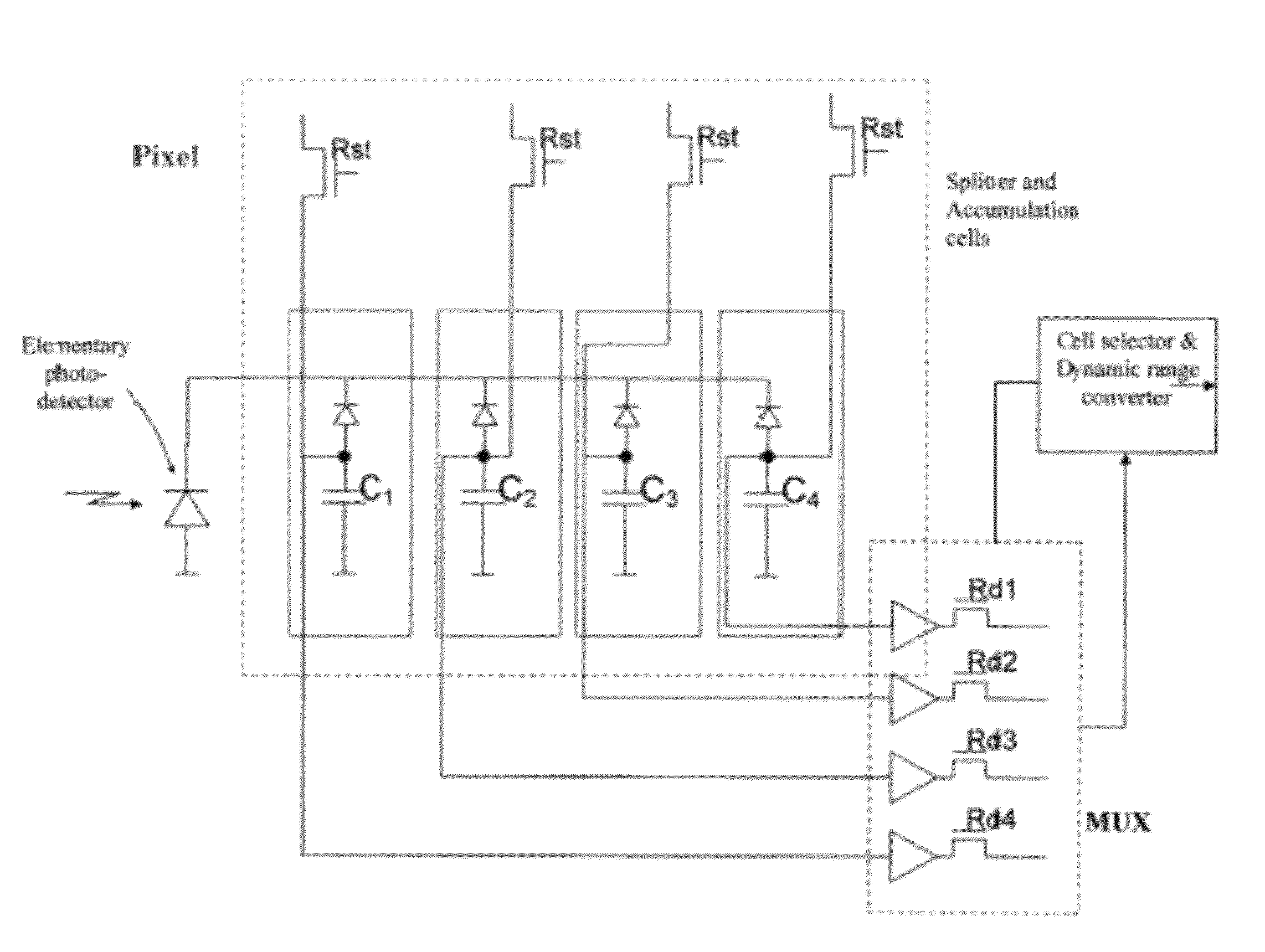
[0057]In FIG. 6, the most appropriate integration time is adjusted for each pixel independently from the integration times of neighboring pixels by associating to each pixel an auto-exposure adjustment circuit that may allow a continuous adjustment with a circuit as shown in FIG. 7 or a selection among a plurality of pre-fixed exposure times with a circuit as shown in FIGS. 8A-8C.

[0058]FIGS. 7 and 8A depict two possible embodiments of a pixel-wise logic control system of exposure of the sensor of this invention.

[0059]FIG. 7 shows a logic circuit like the one that is normally used at sensor level (that is a control of the sole exposure value of all sensitive elements), transposed at p...


PUM


Abstract

A method is provided for obtaining an image with a large dynamic range. An image is acquired such that each image pixel is represented by a plurality of values obtained at the same time but for different integration levels (effective exposures). For each pixel, a representative value is selected among those available, such that it is neither saturated nor blackened.

Description

BACKGROUND[0001]1. Technical Field[0002]This invention relates in general to methods for processing digital images. One embodiment is a method of acquiring a digital image of large dynamic range using a sensor of relatively lower dynamic range capability.[0003]2. Description of the Related Art[0004]Image sensors are used in many types of applications of image acquisition. The two main technologies of image sensors are the so-called CCD (Charge Coupled Devices) and the x-y addressable CMOS devices.[0005]These devices are basically composed of a set or array of photo-detectors that convert the incident light in an electric signal representative of the amount of light impinging on the pixel. The array may be read for producing an image based on the detection pattern of the impinging light. The integration time may be controlled through commonly implemented techniques and usually it is the same for all the photo-detectors of the array.[0006]The dynamic range (briefly DR) of a device for...

Claims


Application Information

Patent Timeline
Patent Type & Authority Patents(United States)
IPC IPC(8): H04N5/228H04N3/14H04N23/40
CPCH04N5/2353H04N5/35554H04N23/73H04N25/583
Inventor CASTORINA, ALFIOCAPRA, ALESSANDRO
Owner STMICROELECTRONICS SRL
Features
  • R&D
  • Intellectual Property
  • Life Sciences
  • Materials
  • Tech Scout
  • Unparalleled Data Quality
  • Higher Quality Content
  • 60% Fewer Hallucinations
Learn More