MIMO radio communication apparatus and method

a radio communication and microphone technology, applied in the field of radio communication apparatus and methods, can solve the problems of large amount of computation in the field of technology, and achieve the effect of maximizing channel capacity and channel capacity

Active Publication Date: 2012-01-24
SAMSUNG ELECTRONICS CO LTD
View PDF34 Cites 21 Cited by
  • Summary
  • Abstract
  • Description
  • Claims
  • Application Information

AI Technical Summary

Benefits of technology

[0011]According to an aspect of the present invention, there is provided a radio communication apparatus including a plurality of reception antennas each having a plurality of antenna patterns; a channel matrix estimation unit for estimating a channel matrix between a plurality of transmission antennas and the plurality of reception antennas; a channel capacity calculation unit for calculating a channel capacity corresponding to a combination of antenna patterns of the plurality of reception antennas by using the estimated channel matrix; and an antenna pattern control unit for changing the antenna patterns of the plurality of reception antennas so that the channel capacity can be maximized.
[0012]According to another aspect of the present invention, there is provided radio communication method including estimating a channel matrix between a plurality of transmission antennas and a plurality of reception antennas each having a plurality of antenna patterns; calculating a channel capacity corresponding to a combination of antenna patterns of the plurality of reception antennas by using the estimated channel matrix; and changing the antenna patterns of the plurality of reception antennas so that the channel capacity can be maximized.

Problems solved by technology

However, this technology requires a large amount of computation until an antenna pattern is determined.

Method used


Image

  • MIMO radio communication apparatus and method
  • MIMO radio communication apparatus and method
  • MIMO radio communication apparatus and method

Examples


Embodiment Construction

[0022]The present invention will now be described more fully with reference to the accompanying drawings, in which preferred embodiments of the invention are shown.

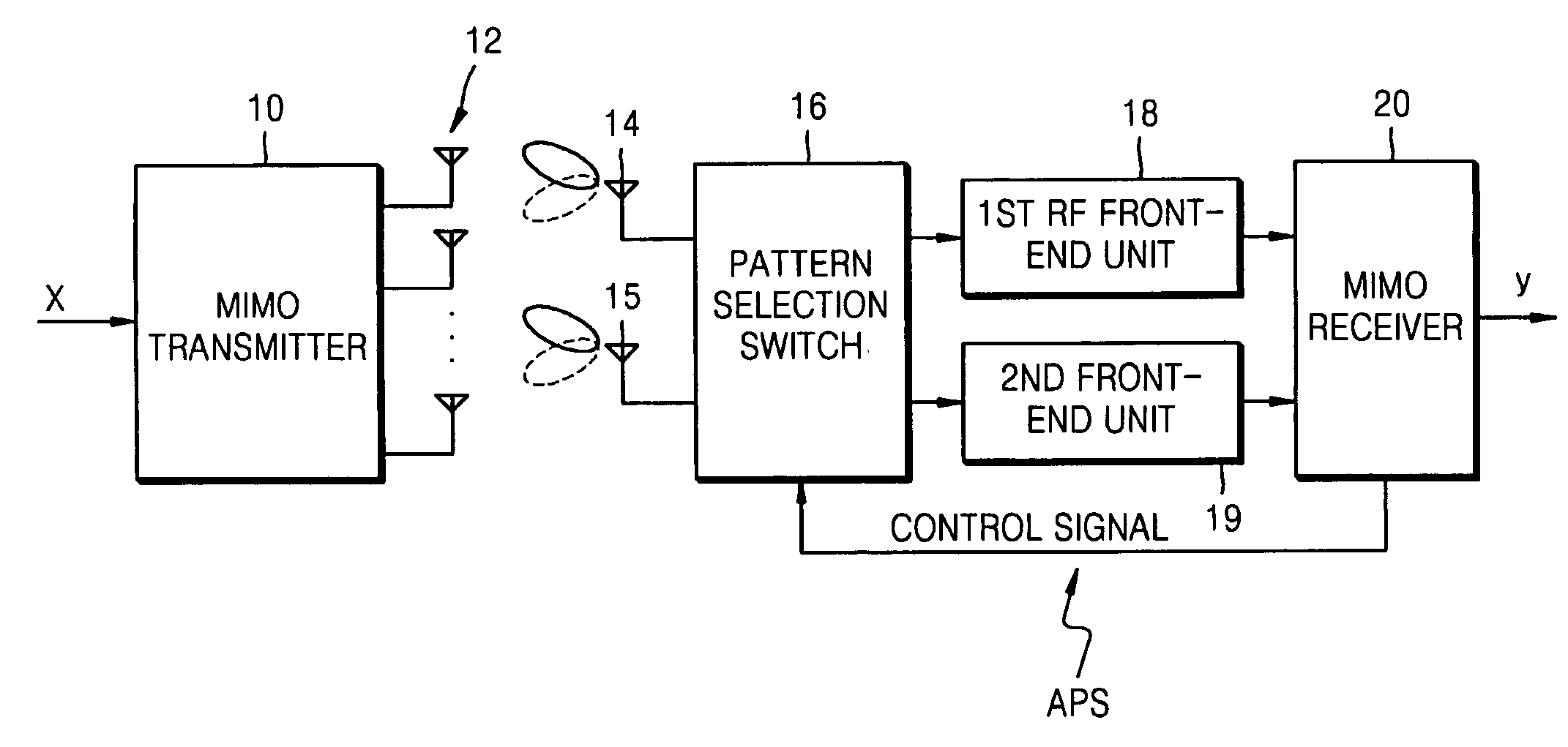
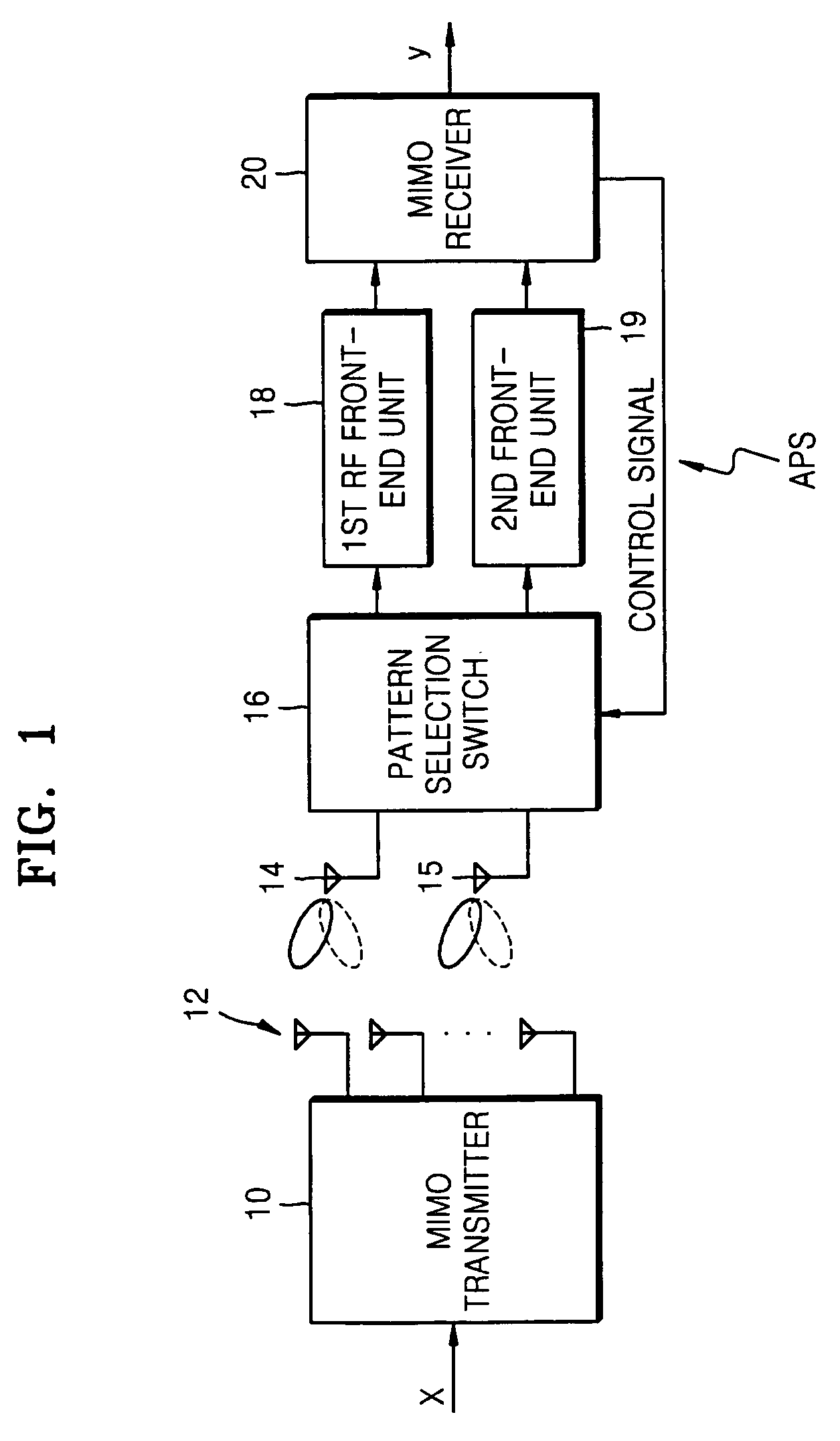
[0023]FIG. 1 is a block diagram illustrating a structure of a radio communication apparatus according to the present invention.

[0024]Referring to FIG. 1, a transmission vector signal (x) is divided in a MIMO transmitter 10 and transmitted to each transmission unit (not shown). The output of each transmission unit is radiated from a plurality of transmission antennas 12.

[0025]The signal radiated from the plurality of transmission antennas 12 is propagated through a transmission path, i.e., a space that can be regarded as parallel multi paths, and arrives at a first reception antenna 14 and a second reception antenna 15. Though the number of reception antennas is being illustrated as 2 for convenience of explanation, the number of reception antennas may be more than 2 and is still within the scope of the present invention.

[...


PUM


Abstract

A multi-input multi-output (MIMO) radio communication apparatus and method are provided. The MIMO apparatus includes a plurality of reception antennas each having a plurality of antenna patterns; a channel matrix estimation unit for estimating a channel matrix between a plurality of transmission antennas and the plurality of reception antennas; a channel capacity calculation unit for calculating a channel capacity corresponding to a combination of antenna patterns of the plurality of reception antennas by using the estimated channel matrix; and an antenna pattern control unit for changing the antenna patterns of the plurality of reception antennas to maximize the channel capacity. According to the MIMO radio communication apparatus and method, direction can be controlled adaptively to a propagation environment.

Description

PRIORITY[0001]This application claims the benefits of Japanese Patent Application No. 2005-362737, filed on Dec. 16, 2005, in Japanese Intellectual Property Office, and Korea Patent Application No. 10-2006-0085369, filed on Sep. 5, 2006, in the Korean Intellectual Property Office, the contents of each which are incorporated herein in their entirety by reference.BACKGROUND OF THE INVENTION[0002]1. Field of the Invention[0003]The present invention relates to a radio communication apparatus and method, and more particularly, to a multi-input multi-output (MIMO) radio communication apparatus and method.[0004]2. Description of the Related Art[0005]One method of increasing a communication capacity without increasing a frequency band, is through the use of multi-input multi-output (MIMO) technology in which a plurality of transmitter antennas are installed. In a space division multiplexing (SDM) method, which is one of the MIMO methods, a data stream to be transmitted is divided into a plu...

Claims


Application Information

Patent Timeline
Patent Type & Authority Patents(United States)
IPC IPC(8): H04H20/67
CPCH04B7/0684H04B7/0845
Inventor YOKOI, ATSUYAMITSUI, TSUTOMU
Owner SAMSUNG ELECTRONICS CO LTD
Why Eureka
Try Eureka