
Windshield wiper device

a wiper device and windshield wiper technology, applied in the direction of lightening support devices, candle holders, monocoque constructions, etc., can solve the problems of multiple assembly manipulations and a large amount of time, and achieve the effect of less tim

Inactive Publication Date: 2012-01-31
ROBERT BOSCH GMBH
View PDF16 Cites 34 Cited by
  • Summary
  • Abstract
  • Description
  • Claims
  • Application Information

AI Technical Summary

Benefits of technology

[0005]The fastening device can have at least one resilient clamping element, which is provided in particular with at least two guide surfaces. A vehicle body panel can be inserted between the at least two guide surfaces. The resilient property of the clamping element makes it possible to compensate for different thicknesses of the vehicle body panel.
[0009]The fastening device can have at least one rubber buffer and / or a spacer sleeve. The rubber buffer also compensates for tolerances in the thickness of the vehicle body panel. The spacer sleeve prevents the rubber buffer from being compressed too much.
[0010]So that the spacer sleeve can reliably prevent the rubber buffer from being compressed too much, said spacer sleeve has an inner hole, which extends tubularly towards the vehicle body panel.
[0011]The snap lever can have an elongated form so that it can be operated easily. It can be locked by a movement, in particular of between 40° and 100°, preferably of between 45° and 95° transverse to its longitudinal axis. In this position, the guide surfaces are spaced apart from one another so that the vehicle body panel can be inserted between the guide surfaces.
[0015]The guide surfaces can be roughed up on their respective facing sides. This increases the friction of the guide surfaces on the vehicle body in a clamped state.

Problems solved by technology

Special tools, multiple assembly manipulations and therefore a relatively great amount of time are required for this.

Method used


Image

  • Windshield wiper device
  • Windshield wiper device
  • Windshield wiper device

Examples


Embodiment Construction

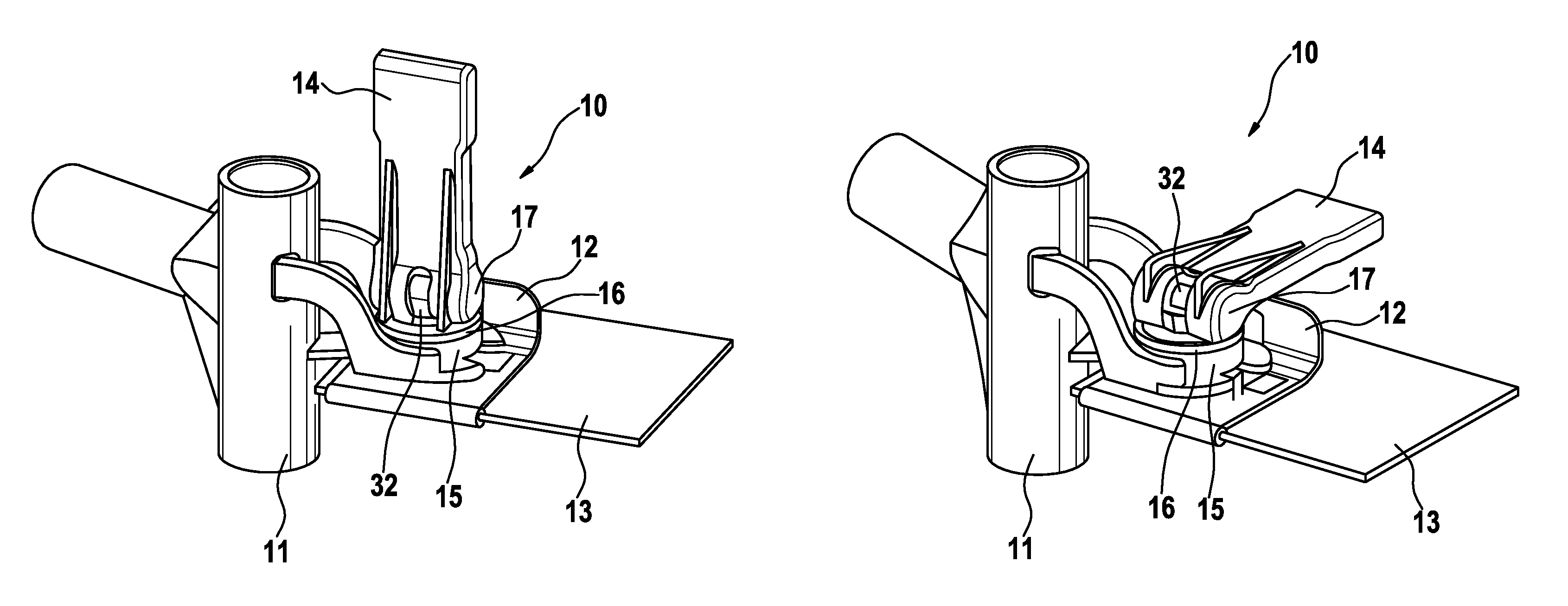
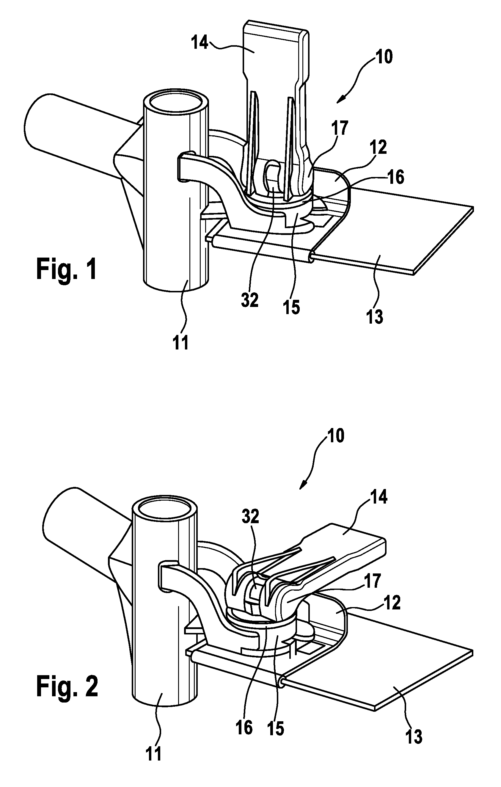
[0027]FIGS. 1 and 2 show a fastening device 10, which is arranged on a molded tube 11. The fastening device 10 has a clamping element 12, between which a vehicle body panel 13 is clamped. In addition, the fastening device 10 is provided with a snap lever 14, a rubber buffer 15 and a spacer sleeve 16.

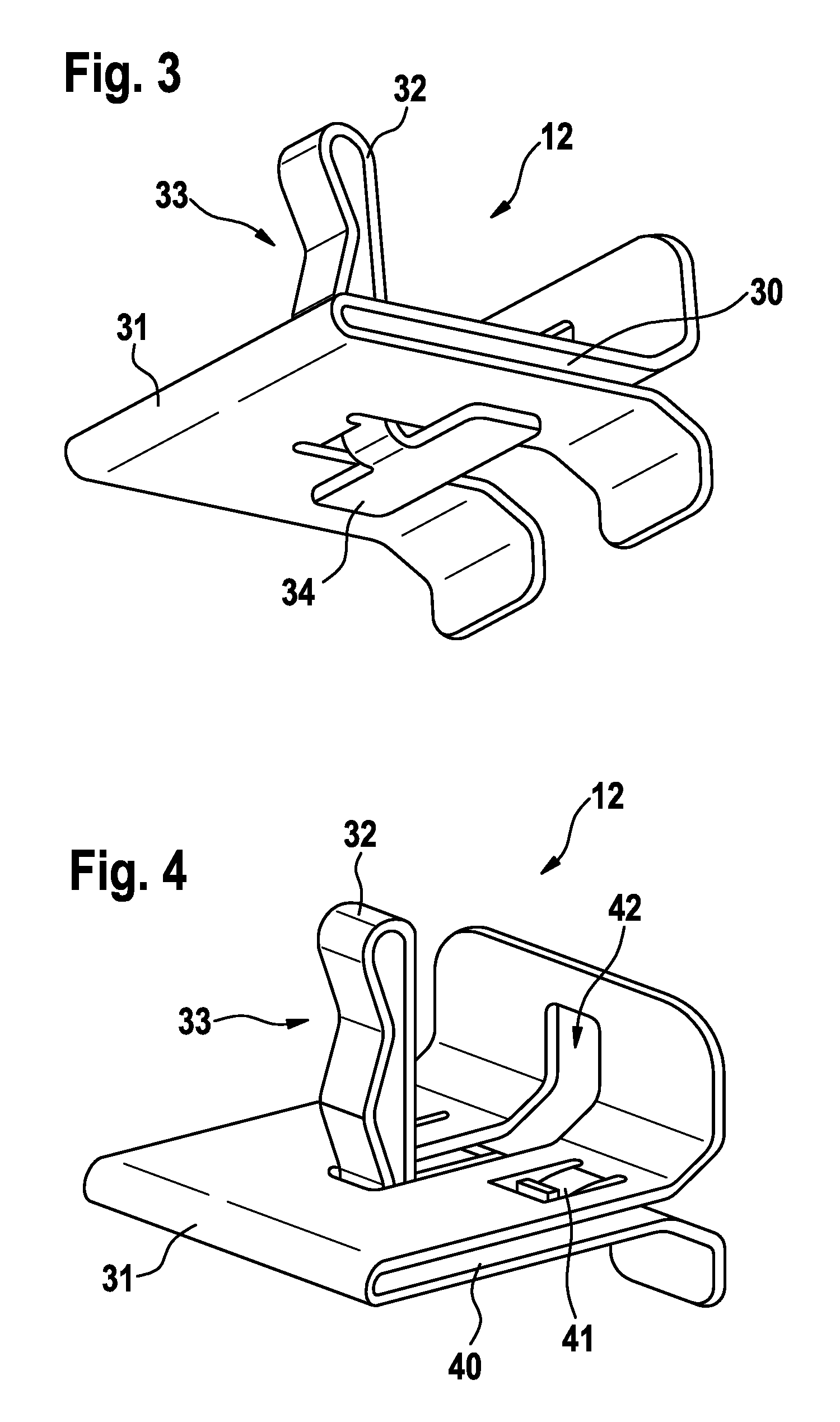
[0028]The clamping element 12 has two guide surfaces 30 (see FIG. 3) and 40 (see FIG. 4), between which the vehicle body panel 13 can be slid. The guide surfaces 30 and 40 are connected resiliently with one another by means of a bent area 31. The bent area 31 also serves as a limit stop for the vehicle body panel 13.

[0029]The clamping element 12 features a bracket 32, which is provided with an undulated region 33. The bracket 32 is provided on its free end with a support element 34, which presses against the underside of the guide surface 40 from below (see FIG. 3).

[0030]The snap lever 14 is positioned eccentrically and pivotably in an axis 17 situated in a bracket 32 (FIGS. 1 and 2).

[00...


PUM


Abstract

The invention relates to a windshield wiper device, in particular for a motor vehicle, comprising a fastening device (10) for fastening the windshield wiper device to the motor vehicle. Until now windshield wiper devices were mainly fastened to the vehicle body by means of screwed connections and plugging locations. The objective of the invention is reducing the assembly effort for fastening the windshield wiper device to the vehicle body. As a result, the inventive windshield wiper device can be clamped firmly to a vehicle body panel (13) by the fastening device (10).

Description

BACKGROUND OF THE INVENTION[0001]The invention relates to a windshield wiper device, in particular for a motor vehicle, comprising a fastening device for fastening the windshield wiper device to the motor vehicle.[0002]Until now windshield wiper devices were mainly fastened to the vehicle body by means of screwed connections and plugging locations. Special tools, multiple assembly manipulations and therefore a relatively great amount of time are required for this.[0003]The objective of the invention is reducing the assembly effort for fastening the windshield wiper device to the vehicle body.[0004]The invention attains the stated objective with a windshield wiper device of the type cited at the outset, which, according to the invention, can be clamped firmly to a vehicle body panel by the fastening device. The windshield wiper device can be fastened to the vehicle body in this way without screws or plugging locations. Consequently, mounting the windshield wiper device requires consi...

Claims


Application Information

Patent Timeline
Patent Type & Authority Patents(United States)
IPC IPC(8): B60S1/06B60S1/04
CPCB60S1/0447B60S1/0433B60S1/0444Y10T403/595Y10T24/44333Y10T24/44368Y10T24/44291B60S1/04
Inventor RITT, JEAN-MARC
Owner ROBERT BOSCH GMBH
Learn More