Sensor device and system having a conveyor and a sensor device

Active Publication Date: 2012-01-31
ROCKWELL AUTOMATION SWITZERLAND
View PDF25 Cites 13 Cited by
  • Summary
  • Abstract
  • Description
  • Claims
  • Application Information

AI Technical Summary

Benefits of technology

[0007]The invention is based on the object of configuring the monitoring of prescribed, in particular dangerous areas with regard to people, for example, to be comparatively easier.
[0018]It is likewise possible to operate at different times. In particular, the monitoring sensors, for example cameras, are synchronized with one another in such a way that each camera is active in a predetermined “time window”. Mutual disturbances between the sensors can thereby be avoided. A mutual influence can also be circumvented by having the sensors operate at different frequencies. In the case of a 3D sensor that evaluates a phase shift of modulated light, different frequencies can be related to a carrier frequency or a modulation frequency.
[0020]In another embodiment of the invention, correction means are provided in order to be able at least approximately to compensate speed differences and / or acceleration differences of points in a plane at an object surface that moves in a normally occurring preferred direction relative to the sensor means. This mode of procedure is a basis for the fact that a plane that is moving toward a camera does not have the same speed and / or acceleration at all locations. A point lying on the optical axis of the camera system moves more quickly toward the camera than a point that is at a distance from the optical axis. This dependence is preferably compensated. To this end, a learning mode may be applied in order to establish the transport direction and the speed of a conveyor. The transport direction can serve to define a Cartesian coordinate system that lies exactly in the transport direction. All recorded images can then be transformed into this coordinate system, something which simplifies the calculation of the speed or the acceleration of object surfaces when the system is in the regular observation mode. It is possible in this way also to compensate the detection of an acceleration of points on an object that is actually moving constantly for points that are at a distance at right angles from the optical axis of the sensor means and therefore have another acceleration than that in the optical axis.
[0024]In another embodiment of the invention, the sensor arrangement is capable of detecting speed patterns and / or acceleration patterns with the aid of one or more learning runs. The sensor arrangement can have recourse to these patterns in order to undertake a comparison with a current speed or acceleration pattern. By way of example, it is thereby possible to distinguish a person from an animal.
[0028]An inventive sensor device can be applied in relation to a danger area not only in the context of a conveyor system. It will also be possible to control the access to a door or a gate to the effect that only objects having a prescribed acceleration and / or speed pattern are given access to a specific space or, in general, that the approach or passage of a person is established. It is possible thereby to control a door movement in a way that the door does not close when the sensor device establishes there are persons in the closing region of the door.

Problems solved by technology

By contrast, others store the reference objects or scenes that can lead to a dangerous situation and consequently require a specific reaction of the machine or the robot.

Method used


Image

  • Sensor device and system having a conveyor and a sensor device
  • Sensor device and system having a conveyor and a sensor device
  • Sensor device and system having a conveyor and a sensor device

Examples


Embodiment Construction

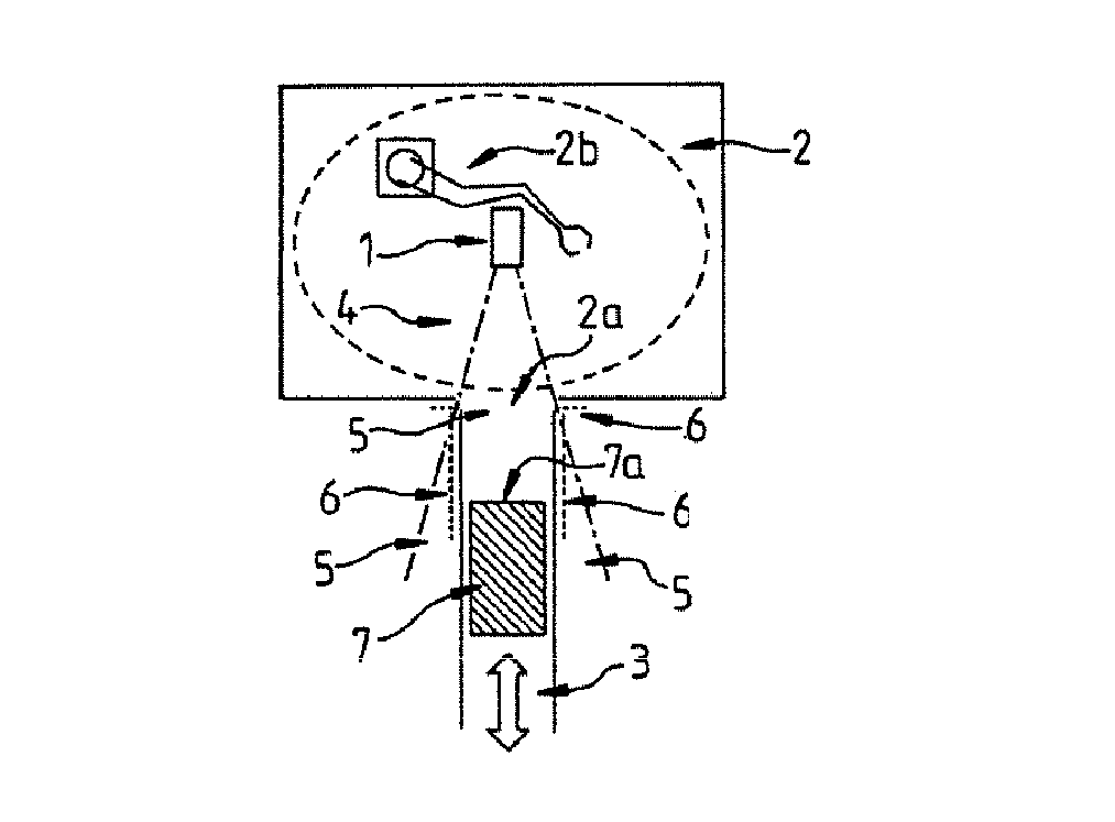
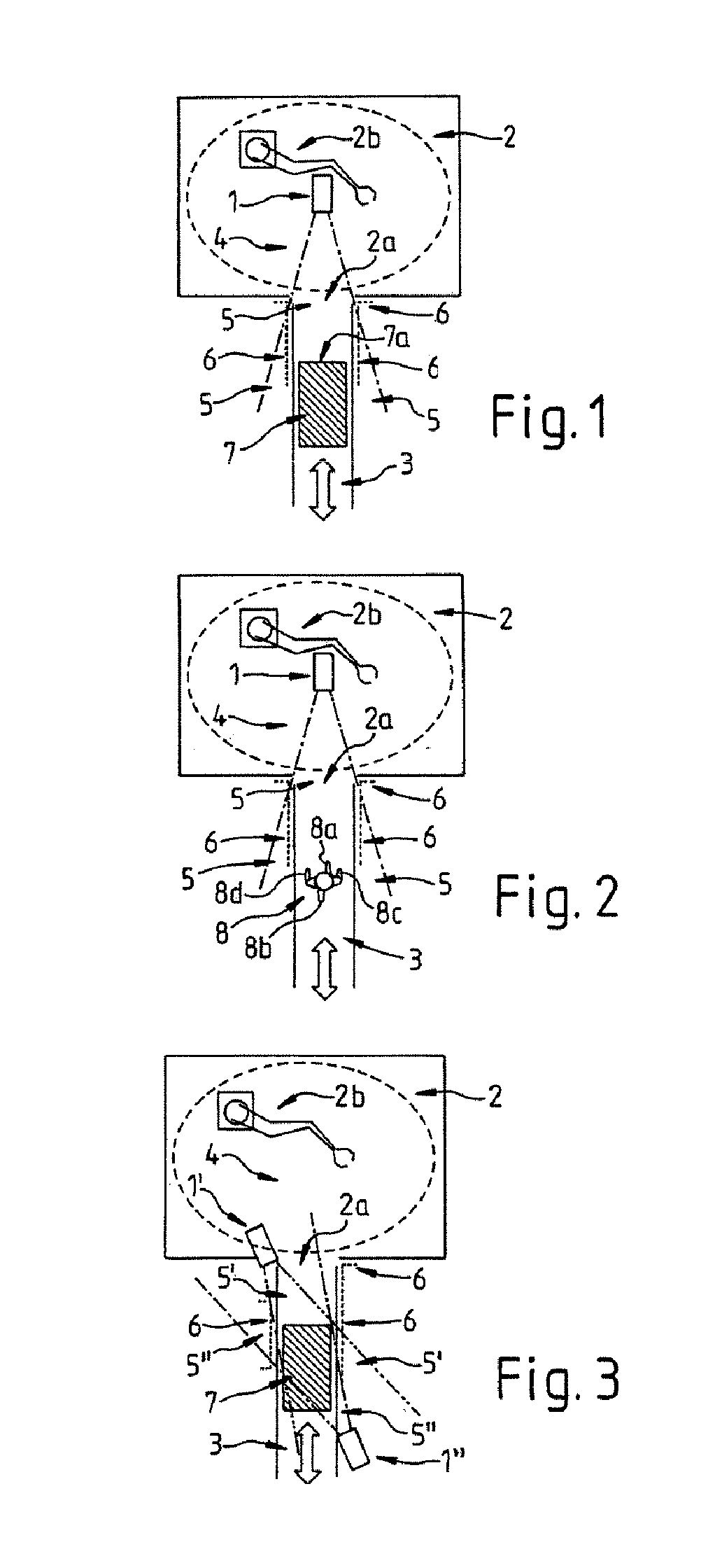
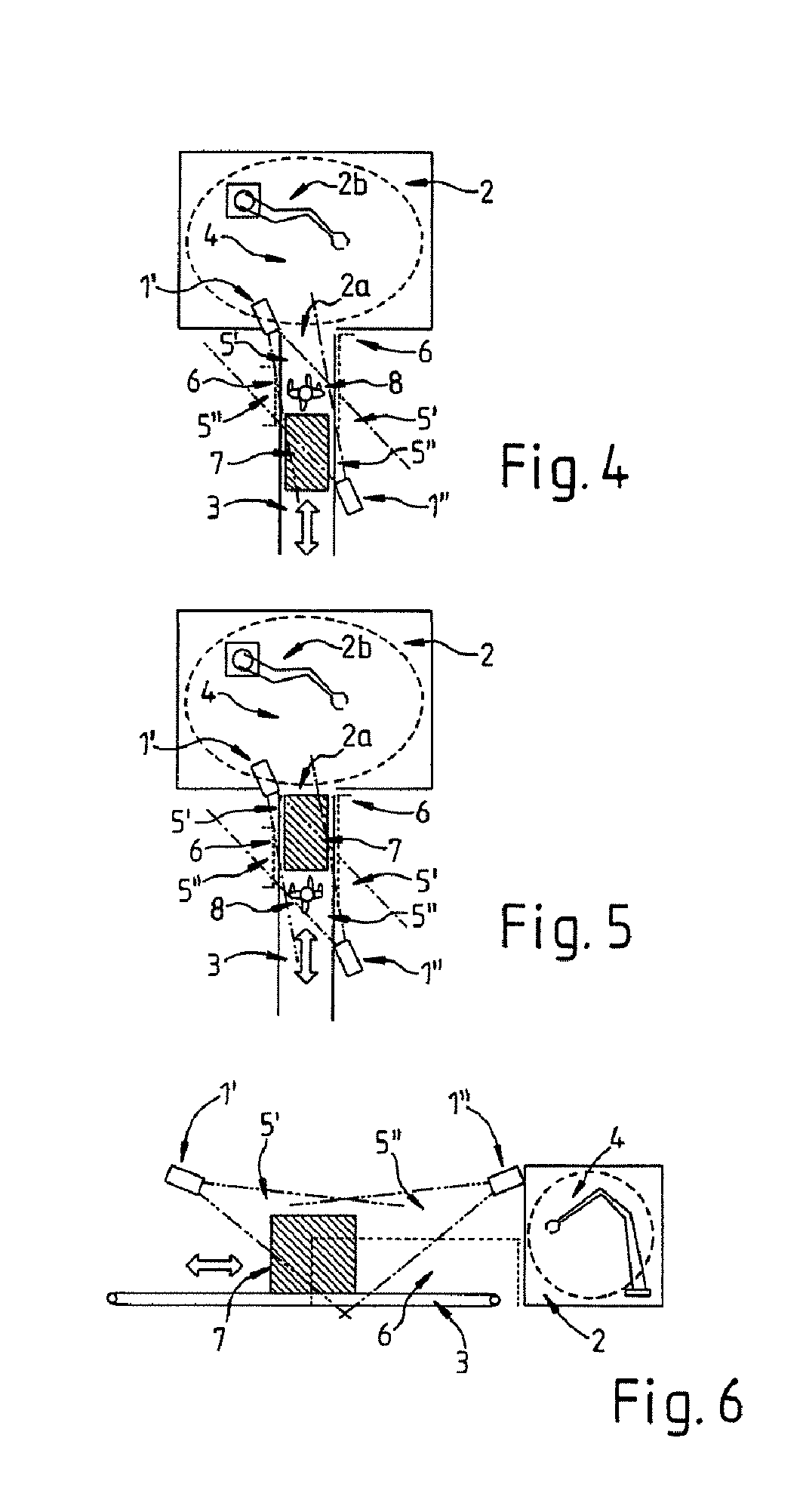
[0035]FIG. 1 shows a robot cell 2 in front of which there is arranged a conveyor belt 3 for supplying it with articles 7. The robot cell 2 has an access area 2a that people may not pass as long as a robot 2b is active.

[0036]FIG. 1 illustrates a situation in which an article 7 is being transported on the conveyor belt 3 in a danger area 4 of the robot 2b over the access area 2a. A 3D camera 1 determines the speed of the article 7. The 3D camera 1 comprises, for example, an optical sensor which determines the distance from an object optically by using the “time of flight” or, for short, “TOF” method. In this case, light is emitted from a light source onto which an oscillation is modulated. Moreover, a sensor is provided with the aid of which the modulated light can be acquired when it is retroreflected by a corresponding surface. The distance from the object at which the light was retroreflected can be determined from the phase difference of the oscillation modulated on between the em...


PUM


Abstract

A sensor device having a sensor arrangement for detecting moving objects that includes a sensor and an electronic unit. The sensor arrangement is designed to detect an object and to subsequently investigate whether there are present within the surface of the object regions that move at a different speed and / or acceleration. The sensor arrangement can also investigate whether the object is accelerating.

Description

CROSS REFERENCE TO RELATED APPLICATIONS[0001]This application is a continuation of International Application No. PCT / EP2008 / 001166, filed Feb. 15, 2008, which designated the United States, and claims the benefit under 35 USC §119(a)-(d) of German Application Nos. 10 2007 011 221.3 filed Mar. 6, 2007 and 10 2007 013 299.0 filed Mar. 16, 2007, the entireties of which are incorporated herein by reference.FIELD OF THE INVENTION[0002]The invention relates to a sensor device comprising sensor means and an electronic unit for detecting moving objects, a system having a conveyor for transporting objects, and a sensor device.BACKGROUND OF THE INVENTION[0003]Industrial production devices frequently comprise robots or machines that are supplied automatically with the material to be processed via a conveyor. Such robots or machines regularly constitute a danger area that is to be monitored with the aid of safety devices. In this case, it is usually necessary for the safety device to be capable ...

Claims


Application Information

Patent Timeline
Patent Type & Authority Patents(United States)
IPC IPC(8): G01P3/36
CPCB25J9/1674G05B19/4061G05B2219/40202G05B2219/40546G05B2219/40554Y02P90/265Y02P90/02
Inventor STEIN, MANFREDMEINHERZ, CARLALBERS, BAS
Owner ROCKWELL AUTOMATION SWITZERLAND
Why Eureka
Try Eureka