Active fixation implantable medical lead configured to indicate via fluoroscopy embedment of helical anchor in cardiac tissue

a technology of active fixation and medical leads, which is applied in the field of active fixation implantable medical leads, can solve the problems of high risk of dislodging of helical anchors from tissue, physician failure to fully embed helical anchors, and inability to determine exactly

Inactive Publication Date: 2012-01-31
PACESETTER INC
View PDF22 Cites 59 Cited by
  • Summary
  • Abstract
  • Description
  • Claims
  • Application Information

AI Technical Summary

Problems solved by technology

An ongoing difficulty with active fixation leads employing helical anchors a physician has no reliable way to determine exactly when the helical anchor is fully embedded into the cardiac tissue at the desired implantation site.
Since it is not possible to determine via fluoroscopy when the helical anchor is fully embedded into the cardiac tissue, it is common for a physician to fail to fully embed the helical anchor into the cardiac tissue.
Indeed, only a portion of the helical anchor may actually be embedded, resulting in a high risk for dislodgement of the helical anchor from the tissue, which would then render the lead incapable of delivering the intended electrical therapy.
Additionally, a helical anchor electrode that is not fully embedded into the cardiac tissue may also cause increased tissue damage to the local tissue adjacent to the helical anchor electrode, thereby resulting in deterioration of the electrical parameters (e.g., pacing capture thresholds, sensing of cardiac signals, etc.).
The opposite situation can also occur and cause therapy malfunction.
The result of such “over-torqueing” can be damage to the lead and, more specifically, the connections (e.g., welds, etc.) between the pin contact and inner conductor coil, the inner conductor coil and the shaft, or the shaft and the helical anchor.
Such coring can significantly increase the risk for damaged tissue at the helical anchor site, resulting in deterioration of the lead's electrical parameters and ultimately the lead's distal tip has a much higher risk of perforating the heart wall.

Method used


Image

  • Active fixation implantable medical lead configured to indicate via fluoroscopy embedment of helical anchor in cardiac tissue
  • Active fixation implantable medical lead configured to indicate via fluoroscopy embedment of helical anchor in cardiac tissue
  • Active fixation implantable medical lead configured to indicate via fluoroscopy embedment of helical anchor in cardiac tissue

Examples


Embodiment Construction

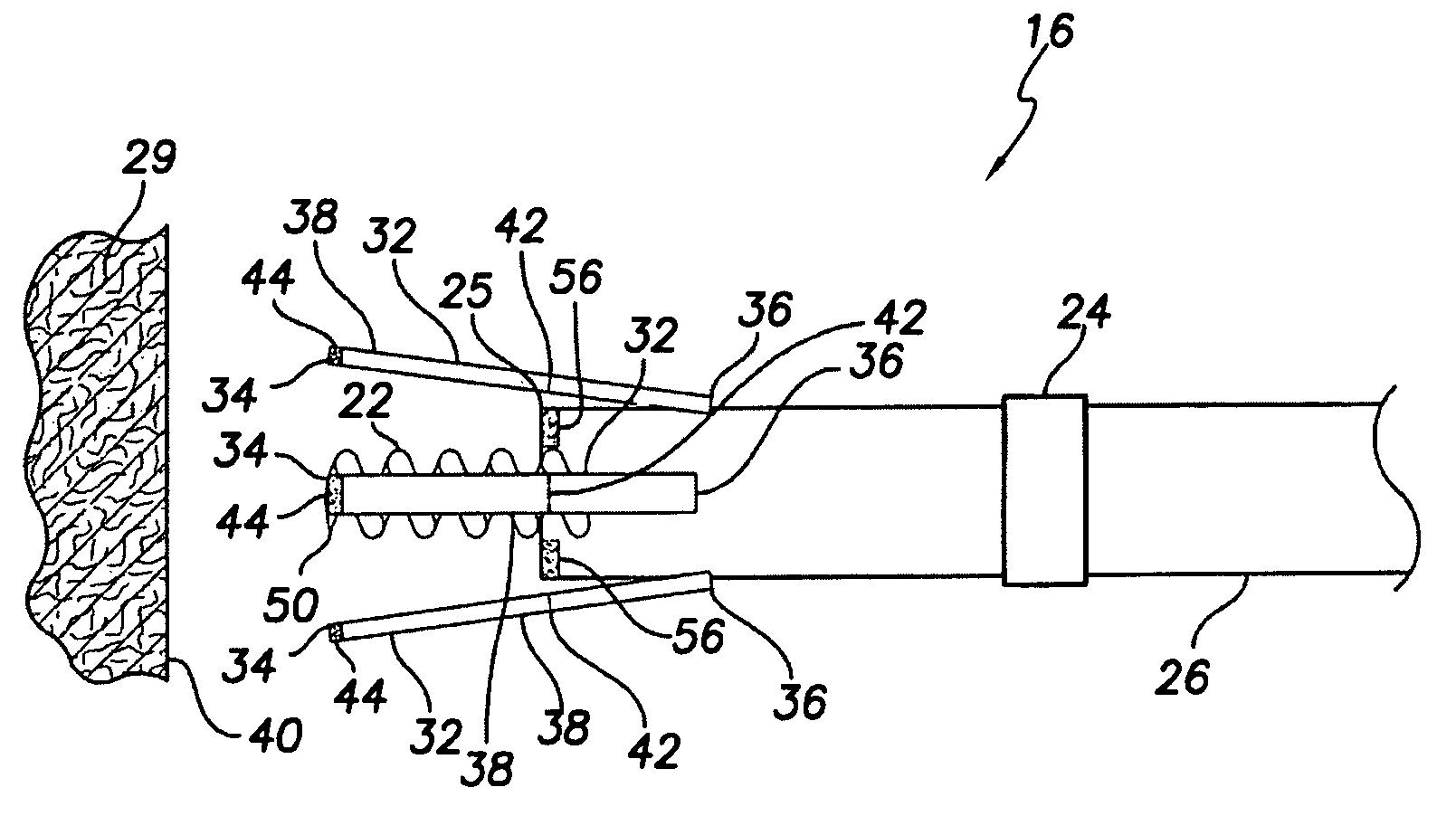
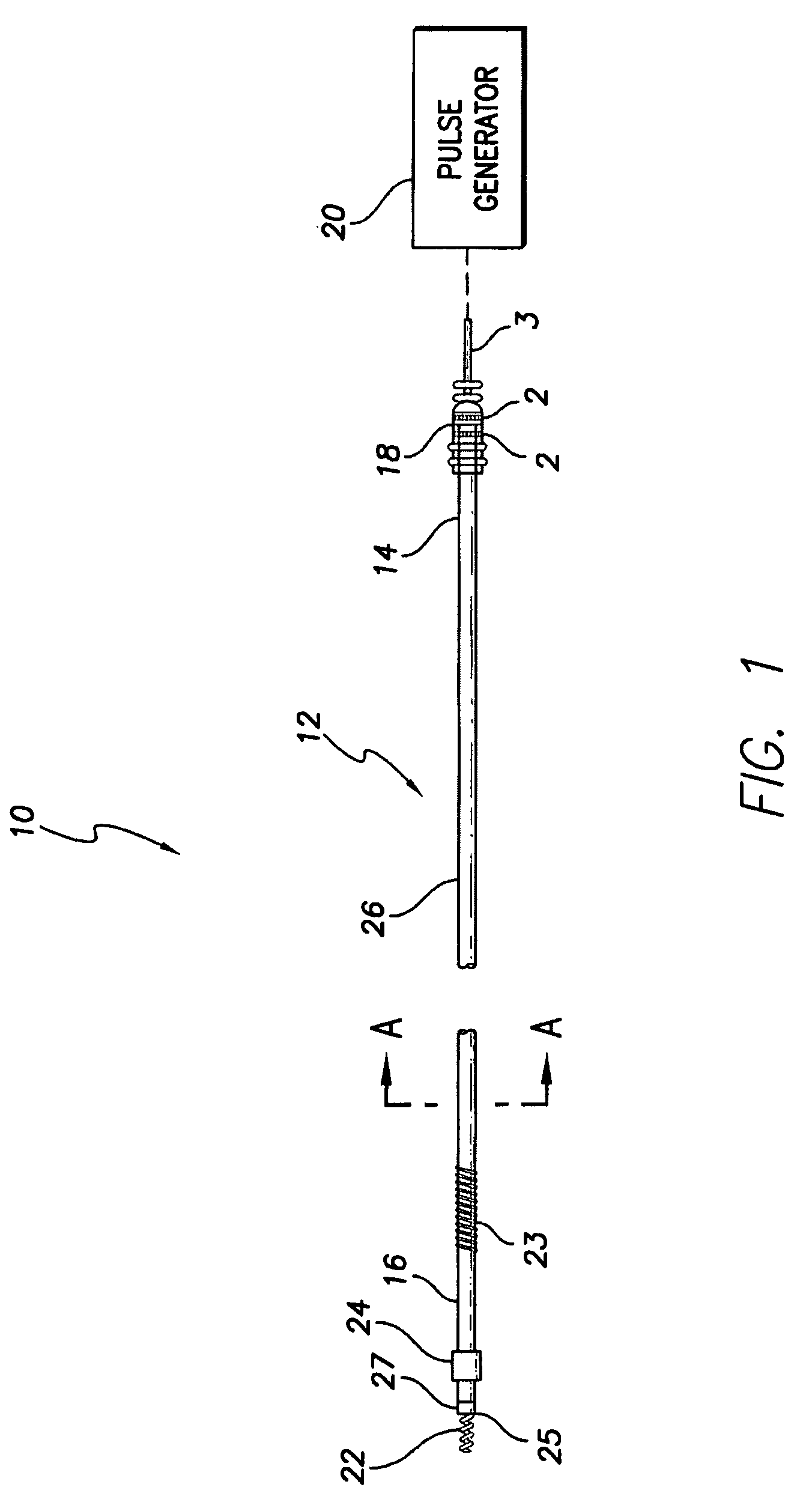
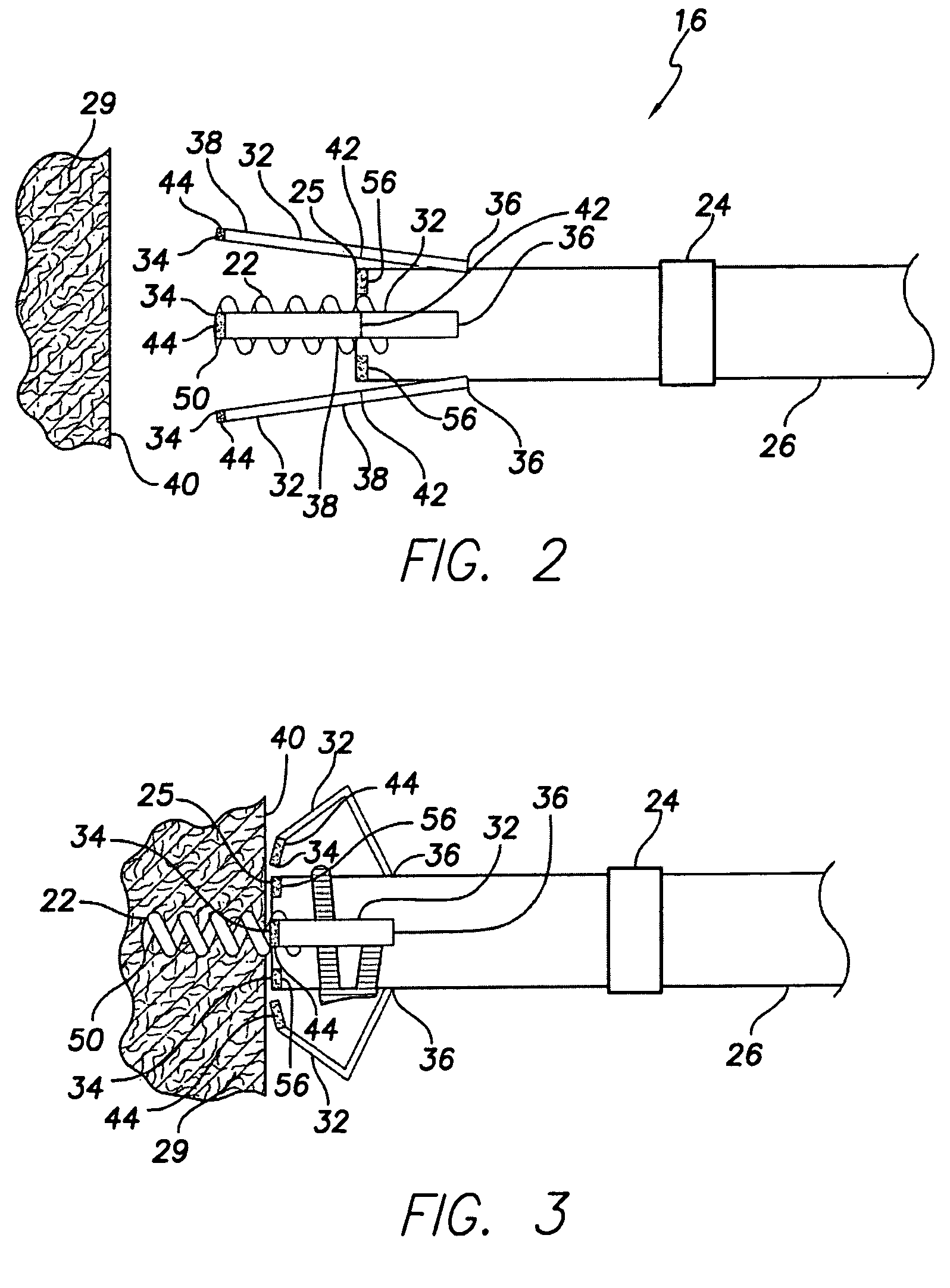
[0024]An implantable active fixation medical lead 10 is disclosed herein. In one embodiment, the lead 10 includes a feature 32, 100 at a distal tip 25 of the lead 10 that allows an implanting physician to determine via fluoroscopy when a helical anchor 22 is fully embedded into the cardiac tissue at the desired implantation site. In one embodiment, the feature 32 may include one or more protuberances 32 with radiopaque markers 44 at the protuberance tips 34 and which move increasingly proximally via contact of the tips 34 with the cardiac tissue surface 40 when the helical anchor 22 is progressively screwed into the cardiac tissue 29. Upon the helical anchor 22 being fully embedded in the cardiac tissue 29, fluoroscopy will show that the radiopaque markers 44 within the protuberance tips 34 move sufficiently proximal such the radiopaque markers 44 will appear flush with other radiopaque markers 56 in the lead distal tip 25.

[0025]In another embodiment, the feature 100 may be a body w...


PUM


Abstract

An implantable medical lead for active fixation to cardiac tissue is disclosed herein. The lead may include a lead body distal end, a tissue fixation helical anchor and a structure. The tissue fixation helical anchor may be coupled to the lead body distal end and include a distal tip. The structure may be coupled to the lead body distal end and include a structure distal end including a first radiopaque marker. The structure may be biased to project the structure distal end near the distal tip. When the tissue fixation helical anchor is progressively embedded in the cardiac tissue, the cardiac tissue progressively displaces the structure distal end proximally.

Description

FIELD OF THE INVENTION[0001]The present invention relates to medical apparatus and methods. More specifically, the present invention relates to implantable medical leads and methods of manufacturing such leads.BACKGROUND OF THE INVENTION[0002]Current active fixation pacing and ICD leads typically employ a tissue fixation helical anchor. Such helical anchors are well known in the art, are the most utilized fixation configuration in cardiac leads, and have been utilized in implantable cardiac leads in cardiac rhythm disease management systems for over 30 years.[0003]A helical anchor is typically located in the distal end of the lead and is mechanically coupled to a shaft within a distal portion of the lead. The shaft is mechanically coupled to the inner coil conductor, which extends through the lead to the lead connector end at the lead proximal end, the lead connector end being configured to mechanically couple to a pulse generator such as, for example, a pacemaker or implantable car...

Claims


Application Information

Patent Timeline
Patent Type & Authority Patents(United States)
IPC IPC(8): A61N1/00
CPCA61N1/0573A61B2090/0807A61B90/39
Inventor HELLAND, JOHN R.
Owner PACESETTER INC
Why Eureka
Try Eureka