Ground Anchor

a ground anchor and lateral load technology, applied in the direction of bulkheads/piles, building types, building constructions, etc., can solve the problems of limited ground anchors that cannot resist lateral loads, in-situ stabilisation is time-consuming, labour-intensive, etc., to achieve effective compression of soil in a given zone, increase the effective diameter of screw flight, and improve the ground holding ability

Inactive Publication Date: 2008-12-11
LEWENHOFF STEPHEN MARK
View PDF31 Cites 24 Cited by
  • Summary
  • Abstract
  • Description
  • Claims
  • Application Information

AI Technical Summary

Benefits of technology

[0032]Without wishing to be limited as to the technical correctness of such beliefs, the inventor believes that reasons as to why the use of a resiliently flexible screw flight provides an improvement in the ground holding ability of a ground anchor, resides in the fact that the pitch of the helical shape is permitted to alter during ground embedment as ground pressure increases. It is believed that the change in pitch effectively compresses the soil in a given zone. Such compression effectively extends the zone of influence of the helical screw beyond the diameter of the helical screw...

Problems solved by technology

Therefore the ability of the ground anchor to resist lateral loads (ie transverse to the longitudinal direction of the anchor shaft) is limit...

Method used


Image

  • Ground Anchor
  • Ground Anchor
  • Ground Anchor

Examples


first embodiment

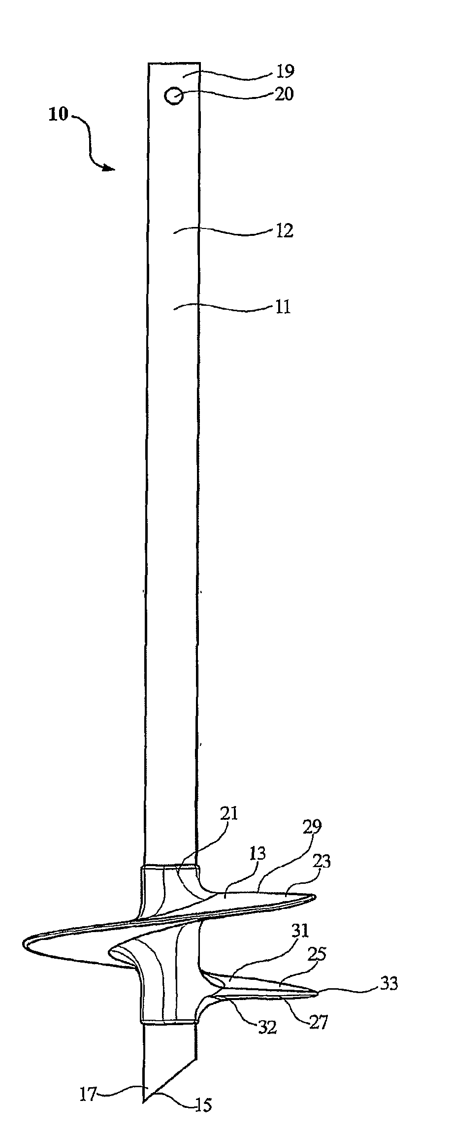
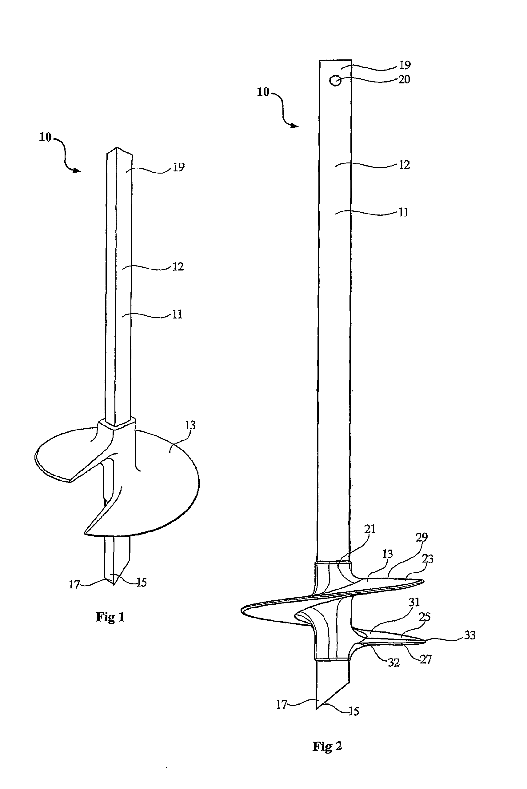
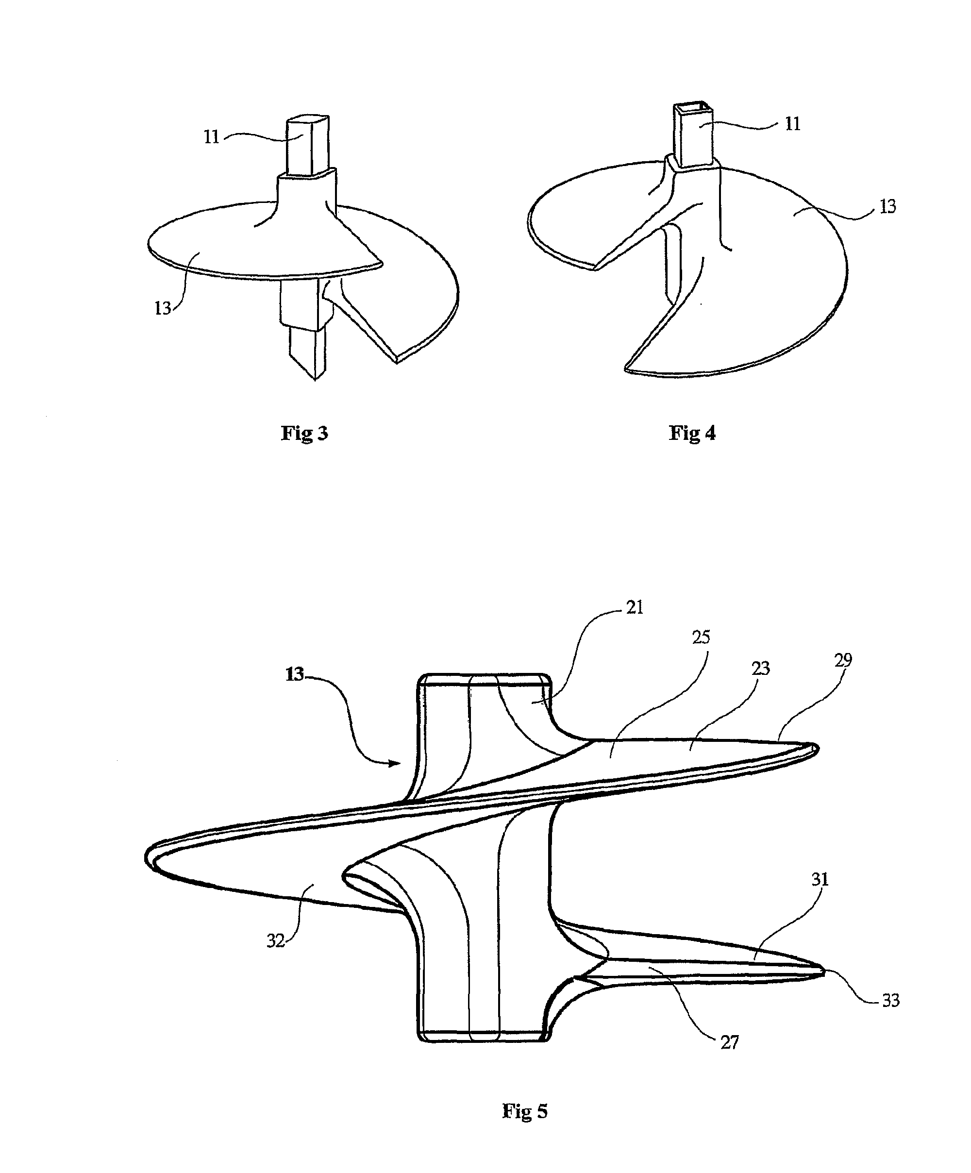
[0079]Referring to FIGS. 1 to 6, there is shown a ground anchor 10 according to a The ground anchor 10 comprises an anchor shaft 11 and an anchoring screw 13 fitted onto the anchoring shaft adjacent the lower end thereof. The anchoring shaft 11 is of polygonal cross-sectional, and in the arrangement shown is of rectangular cross-section with four side walls 12. The anchoring shaft 11 is configured at its bottom end 15 for ground penetration. In the arrangement shown, the bottom end is provided with a point 17 generated by an angular cut on the shaft. The point 17 serves to penetrate the ground and also displace soil sidewardly as it advances through the ground.

[0080]The upper end 19 of the anchor shaft 11 is configured to receive torque applied thereto. The upper end 19 may be configured to receive a tool such as a torque tube through which torque may be applied to the anchor shaft 11. The torque may be applied manually or through a power device, such as for example, a portable ele...

third embodiment

[0095]Referring now to FIG. 8, there is shown an anchoring screw 60 for a ground anchor according to a In this embodiment, the leading edge 27 of the spiral flight 23 is not generally straight (as was the case with the previous embodiments) but rather it is configured to present a curved profile 61 towards the radially outer end thereof. The curved profile 61 comprises a curve which merges with the outer circumference 33. The curved configuration serves to displace rock and debris in the path of the leading edge 27 outwardly away from the rotating helix as it winds into the ground.

fourth embodiment

[0096]With the arrangement shown in FIG. 8, the curved profile 61 can increase the horizontal component of separation between the leading and trailing edges of the screw. In certain circumstances, such separation may be undesirable as it may disrupt the uniformity of loading on the anchoring screw. With a view to addressing this deficiency, the anchoring screw may be configured so that there is some vertical overlap between the leading and trailing edges. Such an arrangement is provided by the next embodiment. Referring now to FIG. 9, there is shown an anchoring screw 70 for a ground anchor according to a In this embodiment, the leading edge 27 incorporates the rounded profile 61 of the previous embodiment but the relative positions of the leading and trailing edges are moved angularly such that there is overlap therebetween.


PUM


Abstract

A ground anchor (10) comprising an anchor shaft (11) and an anchoring screw (13) moulded onto the anchoring shaft adjacent the lower end thereof. The anchoring shaft (11) is of a rectangular cross-section with four side walls (12). The anchoring shaft (11) is configured at its bottom end (15) for ground penetration. The upper end (19) of the anchor shaft (11) is configured to receive torque applied thereto. The anchoring screw (13) comprises a hub (21) and a screw flight (23) on the hub. The anchoring screw (13) is moulded onto the anchor shaft (11), and the hub (21) is keyed to the anchor shaft. The anchoring screw (13) is so constructed that the spiral flight (23) is rigid yet has some resilient flexibility which allows the flight to deflect laterally in the direction of the screw axis. Specifically, the screw flight (23) has sufficient rigidity to allow it to penetrate the ground in which it is intended to be used when torque is applied to the anchor shaft (11). Further, the screw flight (23) has sufficient rigidity in order to retain the ground anchor (10) embedded in the ground when subjected to the normal load conditions for which it is intended, as is the case with conventional ground anchors. The resilient flexibility provides the screw flight (23) with a degree of ‘springiness’, so allowing the screw flight (23) to deflect laterally in the direction of the screw axis when subjected to the loadings to which it is exposed when winding into the ground. With this arrangement, the pitch of the helical screw (25) is permitted to alter during ground embedment as ground pressure increases.

Description

FIELD OF THE INVENTION[0001]The present invention relates to ground anchors, and more particularly to ground anchors employing an anchoring screw to embed the anchor into the ground. Ground anchors are also often referred to as earth anchors.BACKGROUND[0002]Anchors installed in soil are commonly utilised to provide support, either in tension or in compression, and provide support or a tie down point for various equipment and structures. For example, ground anchors are commonly utilised to provide anchorage, in tension, for guy lines used to support electrical transmission equipment. They can also be used to provide a stable surface upon which equipment can be mounted. When this is done, the top of the anchor is normally encased in concrete to provide lateral (ie side to side) stability and the equipment is mounted thereupon.[0003]Ground anchors typically include a helix formed in a spiral configuration around a hub. The helix is rigid and most commonly of metal. Some designs have us...

Claims


Application Information

Patent Timeline
IPC IPC(8): E02D5/80
CPCE02D5/80E02D7/22E04H12/2223E02D5/801
Inventor LEWENHOFF, STEPHEN MARK
Owner LEWENHOFF STEPHEN MARK
Why Eureka
Try Eureka