Laser configured hook column anchors and anchoring systems utilizing the same

a technology of laser configuration and anchoring system, which is applied in the direction of construction, building reinforcement, building components, etc., can solve the problems of uncompromised structural integrity of high-strength metal, and none of the above anchors or anchoring systems provides a laser configured column wall anchor with enhanced interconnection properties and pullout resistance, etc., to achieve low unit cost, simple installation, and low cost

Inactive Publication Date: 2014-12-09
HOHMANN & BARNARD INC
View PDF98 Cites 27 Cited by
  • Summary
  • Abstract
  • Description
  • Claims
  • Application Information

AI Technical Summary

Benefits of technology

[0026]It is another object of the present invention to provide a specialized column anchor that is configured to provide a high-strength interlock between the steel columns and the adjacent wall.
[0027]It is another object of the present invention to provide labor-saving devices to simplify installations of brick, block and stone walls and the securement thereof to a steel column support structure.
[0028]It is a further object of the present invention to provide an anchoring system for a wall comprising a single component that is economical to manufacture resulting in a relatively low unit cost.
[0029]It is a feature of the present invention that when the column anchor is installed within the masonry wall bed joint and the bed joint mortar surrounds the laser configurations and apertures, the column anchor provides high strength pullout resistance from the wall.
[0032]It is yet another feature of the present invention that the column anchor provides a high-strength interconnection within the allowable tolerances for mortar joint anchoring systems.

Problems solved by technology

Precision is also improved because there is no wear of the cutting edge in the process and the structural integrity of the high-strength metal is uncompromised.
On the other hand, contractors find that heavy wire anchors, with diameters approaching the mortar layer height specification, frequently result in misalignment.
Besides earthquake protection requiring high-strength anchoring systems, the failure of several high-rise buildings to withstand wind and other lateral forces has resulted in the promulgation of more stringent Uniform Building Code provisions.
None of the above anchors or anchoring systems provides a laser configured column wall anchor with enhanced interconnection properties and pullout resistance.

Method used


Image

  • Laser configured hook column anchors and anchoring systems utilizing the same
  • Laser configured hook column anchors and anchoring systems utilizing the same
  • Laser configured hook column anchors and anchoring systems utilizing the same

Examples


first embodiment

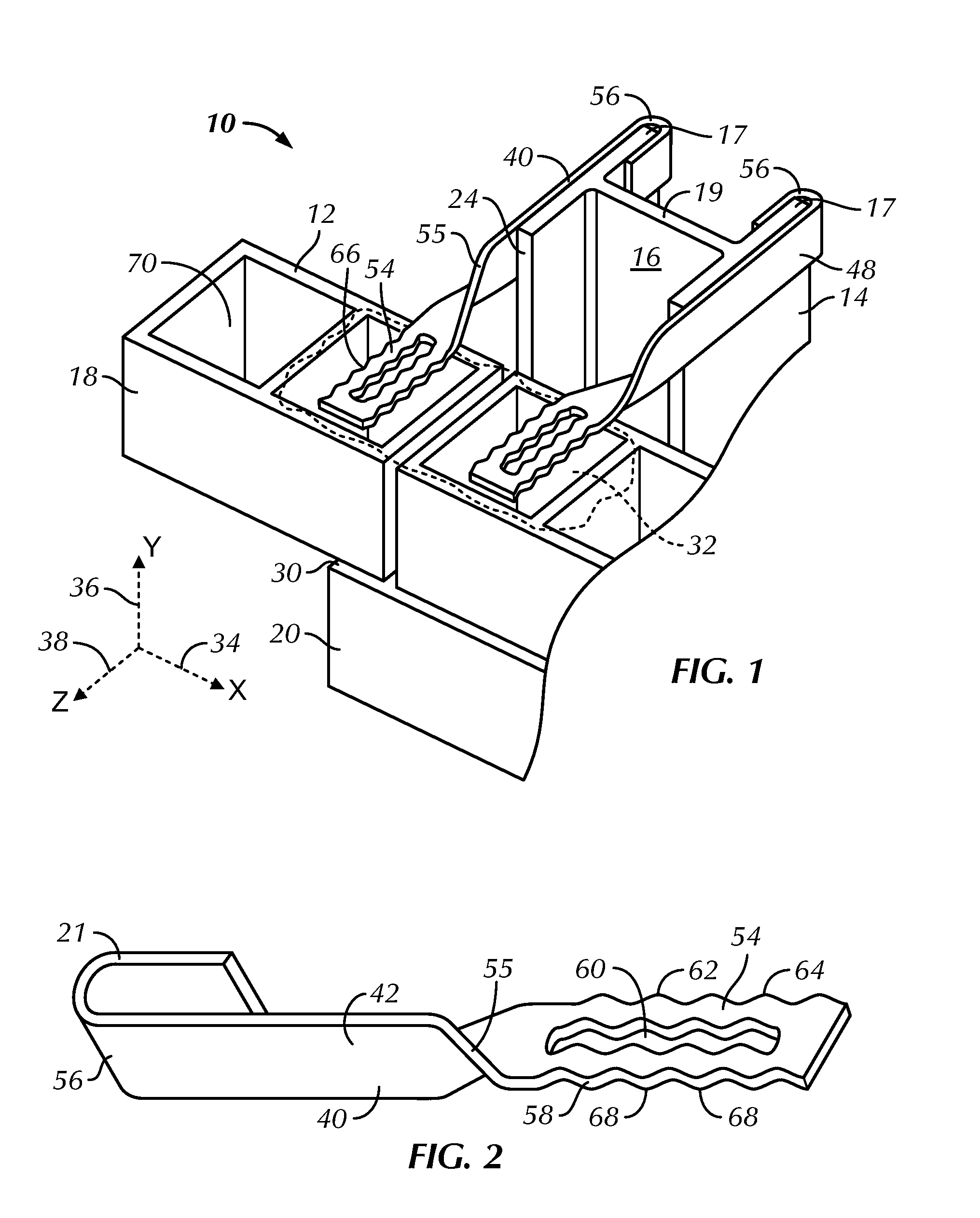
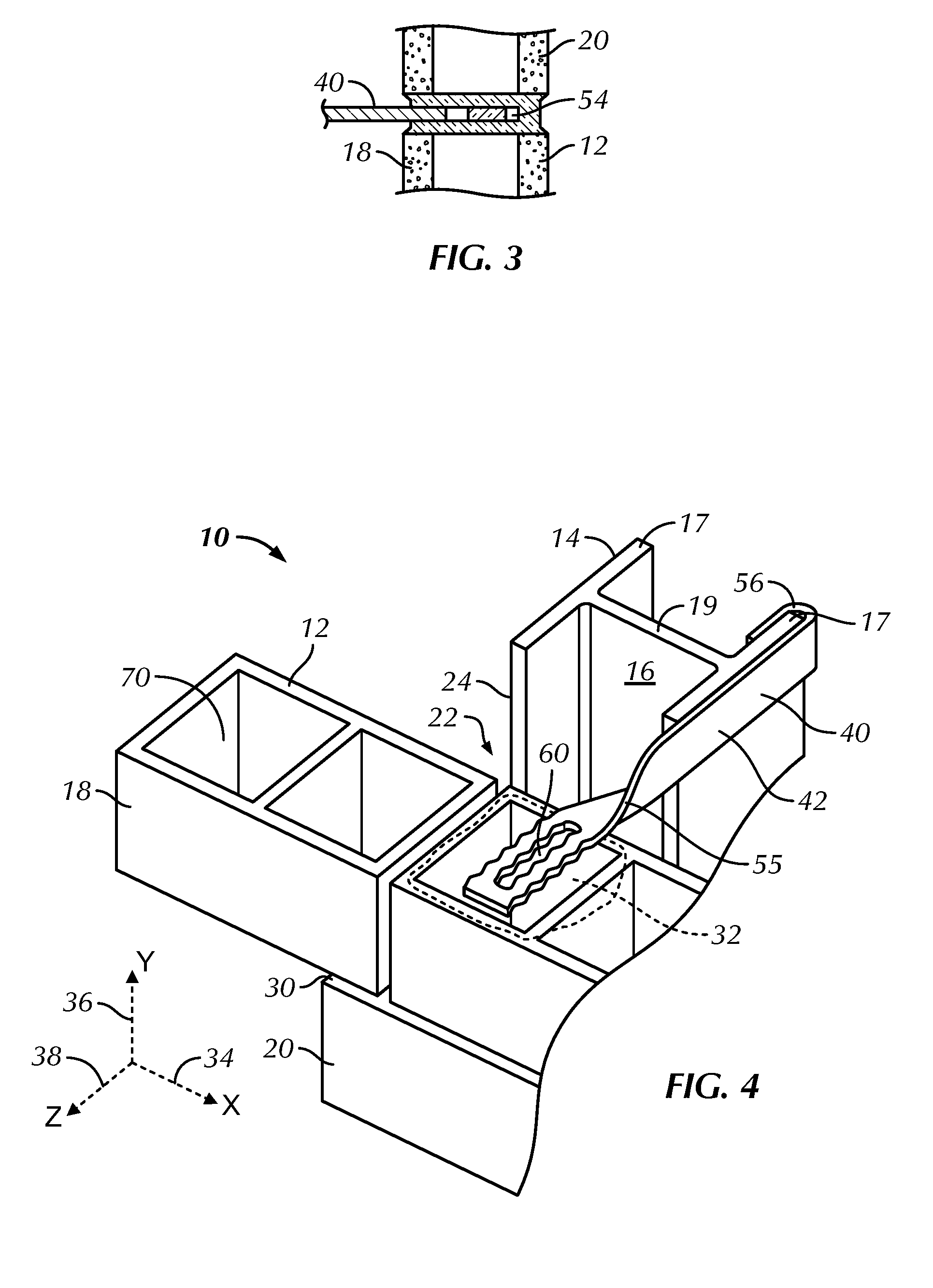
[0047]Referring now to FIGS. 1 through 5, the laser configured column anchors and anchoring system of this invention is shown and is referred to generally by the number 10. In this embodiment, a wall structure 12 is shown having a building column support structure 14 of building columns 16 and an adjacent wall 18 of VCUs 20. The column structure 14 and the wall 18 are spaced apart by a predetermined space 22, which extends outwardly from the surface 24 of the building column structure 14. Optionally, the space 22 accommodates fireproofing (not shown) which is usually sprayed onto the building columns. Each of the building columns 16 has a flange 17 disposed on a central web 19 proximal to the wall 18. The central web 19 is disposed substantially parallel to the face plane of the wall 18. The central web 19 separates and joins the two substantially parallel flanges 17.

[0048]In this embodiment, successive bed joints of mortar 30 and 32 are formed between VCUs 20. Courses of VCUs 20 an...

second embodiment

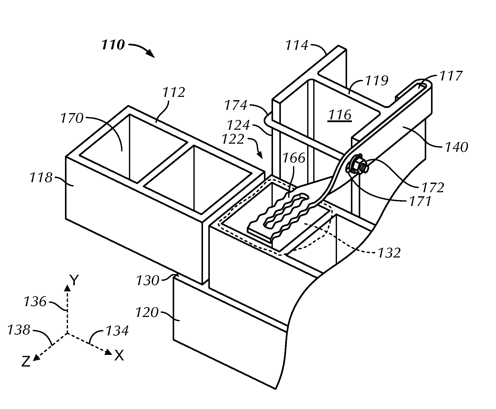
[0054]Referring now to FIGS. 3, and 6 through 9, the high-strength column anchor and anchoring system is shown and is referred to generally by the numeral 110. In this embodiment, a wall structure 112 is shown having a building column support structure 114 of building columns 116 and an adjacent wall 118 of VCUs 120. The building column structure 114 is shown spaced from the wall 118. The surface 124 of the building column structure 114 lies substantially in a plane parallel to that of the adjacent surface of wall 118. Each of the building columns 116 has a flange 117 disposed on a central web 119 proximal to the wall 118. The central web 119 is disposed substantially parallel to the face plane of the wall 118. The central web 119 separates and is joined to the two substantially parallel flanges 117.

[0055]In this embodiment, successive bed joints of mortar 130 and 132 are formed between VCUs 120. Courses of VCUs 120 and the bed joints 130 and 132 are substantially planar and horizon...


PUM


Abstract

A high-strength laser configured column anchor and anchoring system is disclosed. The high-strength column anchor provides high-strength pullout resistance when embedded within the wall bed joint. Specially-configured apertures, edging and dimension restrictions provide for flow-through mortar embedment within the wall bed joint. The edging provides irregular and regular patterns ensuring a secure fit within the bed joint. The column anchors include a hook attachment portion for secure attachment to the column flanges and optionally include a securement bar or clamp to further secure the column anchor to the column flanges.

Description

BACKGROUND OF THE INVENTION[0001]1. Field of the Invention[0002]This invention relates to an improved anchoring arrangement for use in conjunction with building construction having a masonry wall secured to steel building column supports. More particularly, the invention relates to construction accessory devices, namely, specially-configured hook column anchors with laser carve-outs that provide high strength pullout resistance when secured to the columns and within the masonry wall bed joints. The invention is applicable to structures having walls constructed from brick, block or stone in combination with a building column support.[0003]2. Description of the Prior Art[0004]In the past, investigations relating to the effects of various forces, particularly lateral forces, upon brick veneer masonry construction demonstrated the advantages of having high-strength anchoring components embedded in the bed joints of anchored walls, such as facing brick, block or stone wall. Anchors are g...

Claims


Application Information

Patent Timeline
Patent Type & Authority Patents(United States)
IPC IPC(8): E04C5/00E04B1/41
CPCE04B1/41E04B1/4178
Inventor HOHMANN, JR., RONALD P.HOHMANN, RONALD P.
Owner HOHMANN & BARNARD INC
Why Eureka
Try Eureka