
Heating, ventilation, air conditioning and refrigeration system with multi-zone monitoring and diagnostics

a refrigeration system and multi-zone technology, applied in the field of heating, ventilation, air conditioning and refrigeration (hvac & r) systems, can solve problems such as discomfort for occupants of clime controlled zones, difficulty in diagnosing a malfunctioning system component, and secondary system damage to other components

Inactive Publication Date: 2012-02-07
CARRIER CORP
View PDF14 Cites 6 Cited by
  • Summary
  • Abstract
  • Description
  • Claims
  • Application Information

AI Technical Summary

Benefits of technology

The present invention is a system for periodically evaluating and diagnosing the performance of various components in a refrigeration system, such as refrigeration valves, air dampers, and air side economizers. This is done by switching each component between ON and OFF positions and observing changes in operating parameters, such as refrigerant suction pressure and air supply temperature. The diagnostics are based on the reliability of each component and can be transmitted to a remote maintenance site for analysis and maintenance. The invention allows for efficient and cost-effective evaluation of system performance.

Problems solved by technology

In such a complex refrigerant system, it is difficult to diagnose a malfunctioning system component.
If such a problem is not identified and isolated in a timely manner, the malfunctioning or broken component can cause secondary system damage to other components.
Also, malfunctioning equipment in one zone may affect operation of system components in the other zones causing discomfort to the clime controlled zone occupants.
These components could malfunction, and it is a difficult task to pinpoint the root cause of a problem during troubleshooting in a timely and cost effective manner.

Method used


Image

  • Heating, ventilation, air conditioning and refrigeration system with multi-zone monitoring and diagnostics
  • Heating, ventilation, air conditioning and refrigeration system with multi-zone monitoring and diagnostics

Examples


Embodiment Construction

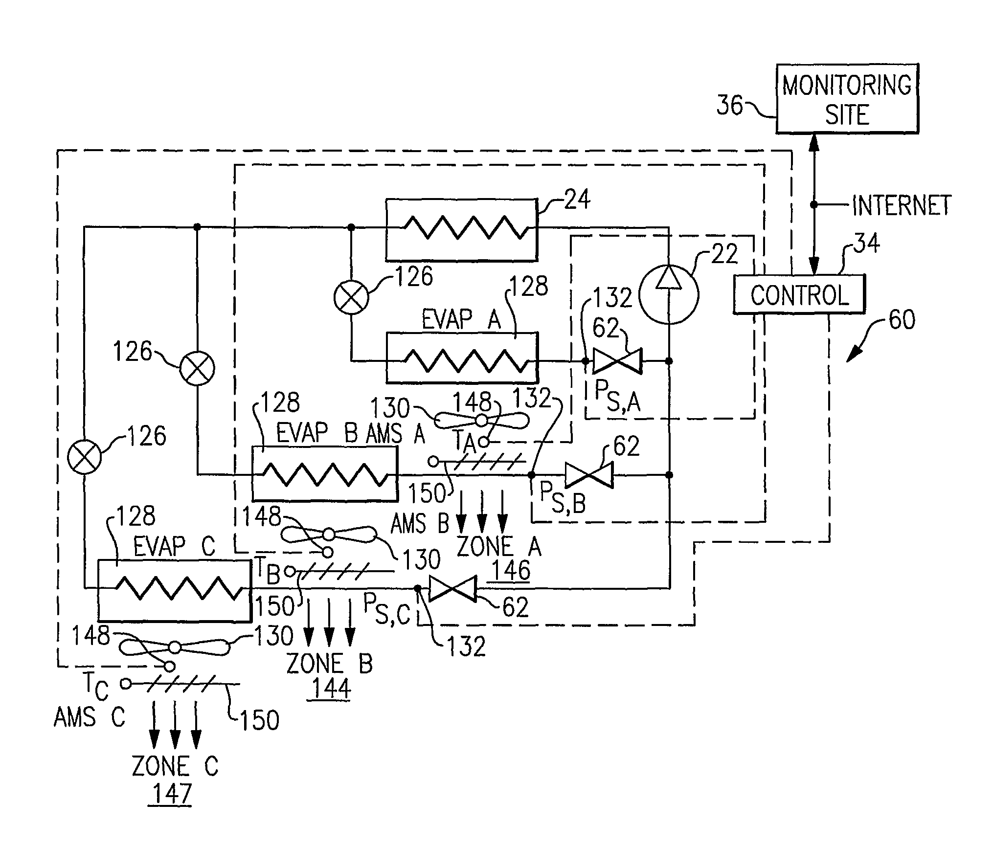
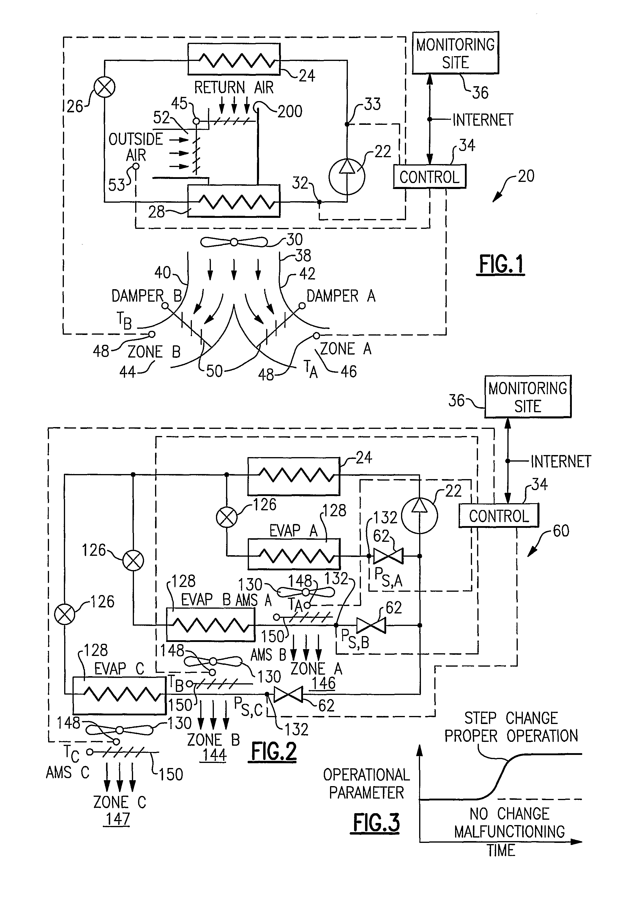
[0015]FIG. 1 shows a refrigerant system 20 having a compressor 22 compressing a refrigerant and delivering the refrigerant to a condenser 24. An expansion device 26 is positioned downstream of the condenser 24, and an evaporator 28 is positioned downstream of the expansion device 26, both with respect to refrigerant flow throughout the system. An air mover such as a fan 30 blows air over the evaporator 28 and delivers the air into a common air supply duct 38 leading to separate ducts 40 and 42 delivering the conditioned air into separate climate controlled zones 44 and 46. As known, temperature sensors 48 are positioned within each climate controlled zone to sense the temperature of the air in the zone. Similarly, humidity or carbon dioxide sensors (not shown) may be located within individual air supplied ducts 40 and 42 or within climate controlled zones 44 and 46. Dampers 50 are controlled by a main system control 34 (or a separate control communicating with the main system contro...


PUM


Abstract

A multi-zone HVAC&R system has its control programmed to provide diagnostic testing of air handling components and refrigerant components associated with each climate controlled zone in sequence. The control changes the original position of the corresponding component and a resultant change in a relevant operational parameter is sensed. If the actual change is outside of the tolerance band associated with the expected change, then the determination is made that the component under consideration is malfunctioning. The periodicity of a diagnostic procedure for a particular component is typically defined by its criticality and reliability level. If the change in the corresponding operation parameter is recorded and stored in the database, the component degradation can be observed over time and a prognostic prediction can be made when a particular component requires preventive maintenance or replacement.

Description

[0001]This application is a United States National Phase application of PCT Application No. PCT / US2006 / 041572 filed Oct. 23, 2006.BACKGROUND OF THE INVENTION[0002]This application relates to a heating, ventilation, air conditioning and refrigeration (HVAC&R) system in which conditioned air is delivered to a plurality of climate controlled zones, and wherein a monitoring and diagnostic test procedure is provided for system components associated with each of the climate controlled zones.[0003]Refrigerant systems are known, and are utilized in many applications, such as air conditioning, refrigeration and heat pump systems, to condition (maintain the temperature and humidity) of air being delivered into a climate controlled environment. Other secondary fluids (rather than air), such as water or glycol, can be utilized as well. A single refrigerant system that provides conditioned air to a plurality of distinct climate controlled zones is not an uncommon application in the modern HVAC&R...

Claims


Application Information

Patent Timeline
Patent Type & Authority Patents(United States)
IPC IPC(8): F25D17/06
CPCF24F11/0012F24F11/0086F25B49/005G01K13/00G01K15/00G01K15/007F25B2500/06F24F11/30F24F2110/10F24F11/38
Inventor TARAS, MICHAEL F.LIFSON, ALEXANDER
Owner CARRIER CORP
Learn More