Electric rotating machine

a technology of rotating machines and rotating parts, which is applied in the direction of magnetic circuit rotating parts, magnetic circuit shape/form/construction, windings, etc., can solve the problems of enlarged risk of breakage of outgoing leads and difficulty in striking a good balance, and achieve the effect of simplifying the connection of outgoing leads and high productivity

Active Publication Date: 2012-02-07
MITSUBISHI ELECTRIC CORP
View PDF10 Cites 12 Cited by
  • Summary
  • Abstract
  • Description
  • Claims
  • Application Information

AI Technical Summary

Benefits of technology

[0012]The present invention has been implemented in order to solve the foregoing problems in a conventional electric rotating machine; the objective thereof is to provide a high-reliability and high-productivity electric rotating machine that is obtained by securing the coolability of the switching element and simplifying the connection of outgoing leads and the like.
[0014]The electric rotating machine is provided with an intermediate plate having a power circuit connection portion that is connected with an outgoing lead drawn out from a power circuit unit and an armature winding connection portion that is connected with the power circuit connection portion and an outgoing lead drawn out from an armature winding. Therefore, the power circuit connection portion and the armature winding connection portion can be arranged at desired positions and outgoing leads from the armature winding of the stator are drawn out in such a way as to fall within a given space, so that intermediate connection lines for connecting windings can be shortened. Accordingly, not only the breakage of an intermediate connection line caused by a vibration can be prevented, but also the switching elements can separately be arranged so as to reduce thermal interference between the switching elements; therefore, the switching elements can effectively be cooled.

Problems solved by technology

Accordingly, in a conventional in-vehicle electric rotating machine, it has been difficult to strike a good balance between shortening the phase-to-phase connection outgoing leads and the neutral-point outgoing leads and effectively cooling the switching elements.
In contrast, in the case where, in order to effectively cool the switching elements, the heat sinks to which the switching elements are fixed are arranged in a dispersed manner around the center axis of the electric rotating machine, the positions of the outgoing leads for connecting the switching elements and the diodes are dispersed; as a result, the lengths of the phase-to-phase connection outgoing leads and the neutral-point outgoing leads become large, whereby the risk of the breakage of these outgoing leads is enlarged.

Method used


Image

  • Electric rotating machine
  • Electric rotating machine
  • Electric rotating machine

Examples


embodiment 1

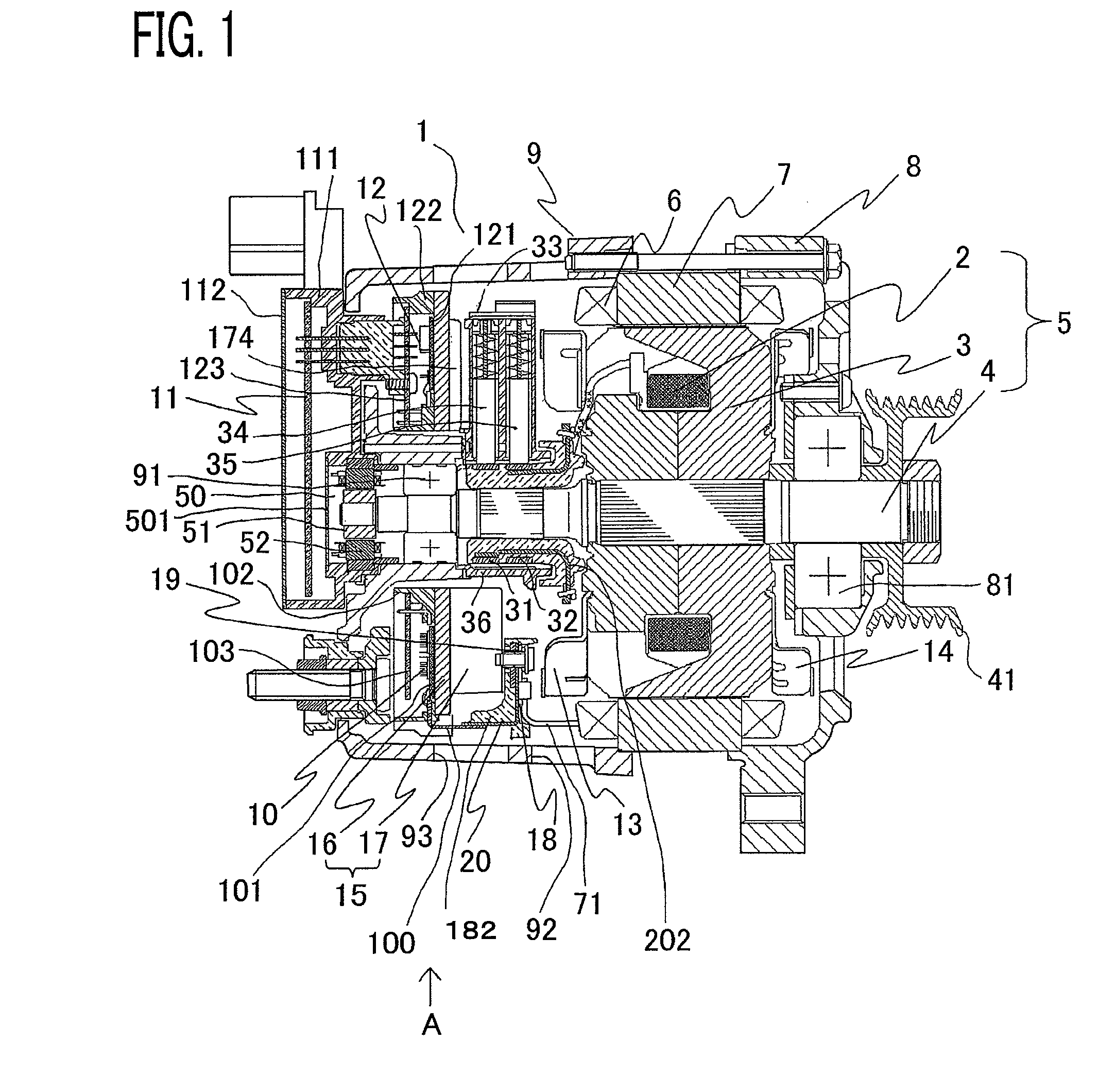
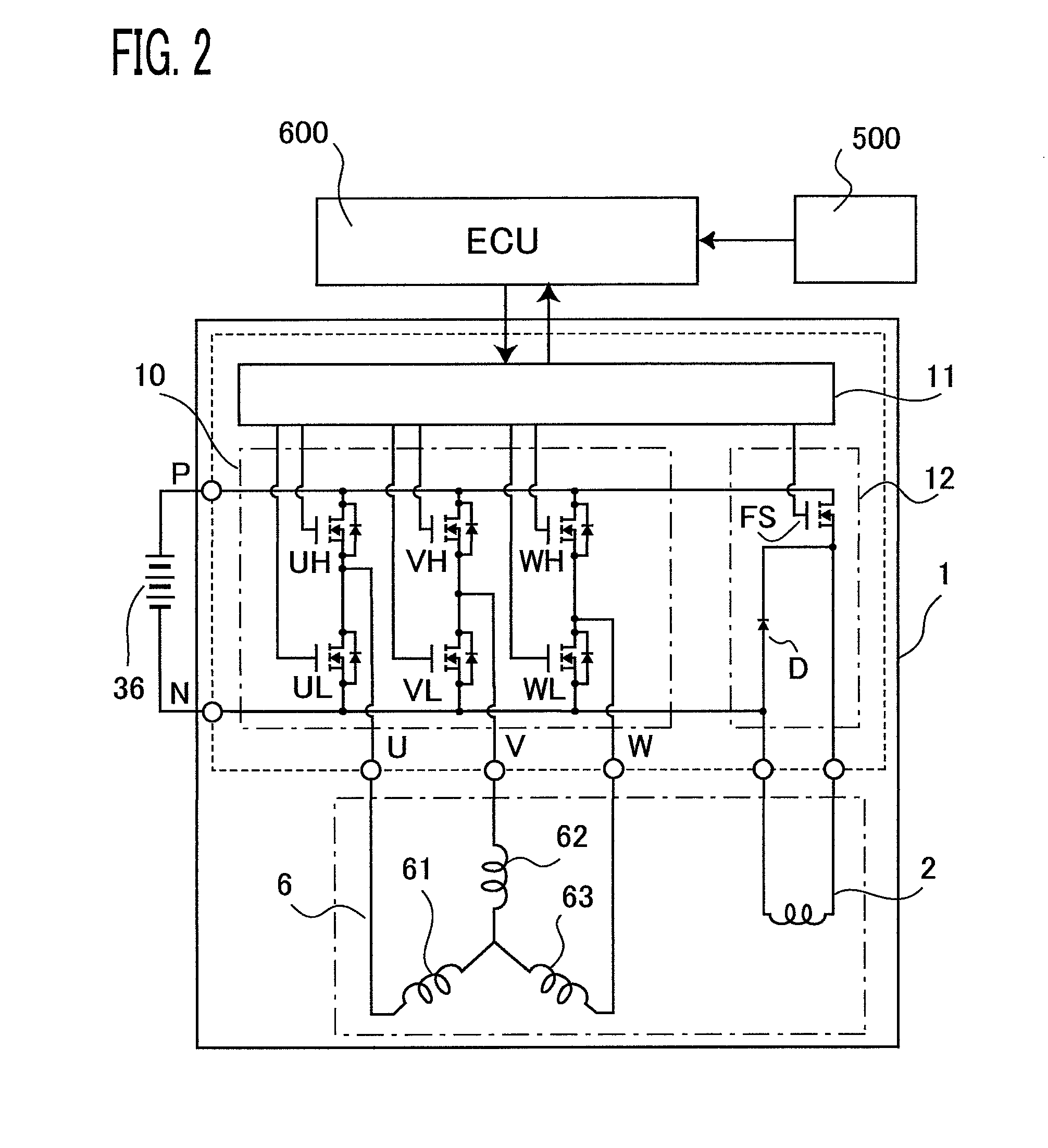
[0023]An in-vehicle electric rotating machine according to Embodiment 1 of the present invention will be explained below with reference to the accompanying drawings. FIG. 1 is a longitudinal cross-sectional view of an in-vehicle electric rotating machine according to Embodiment 1 of the present invention; FIG. 2 is an electric circuit diagram of an in-vehicle electric rotating machine according to Embodiment 1 of the present invention. In the following explanation, one side, of an in-vehicle electric rotating machine, at which a pulley to be coupled with the output axle of an engine is provided will be referred to as the “front-side”, and the other side opposite to the front-side will be referred to as the “rear-side”. In FIGS. 1 and 2, an in-vehicle electric rotating machine 1 is provided with a front-side housing 8, a rear-side housing 9, a rotor 5 whose shaft 4 is pivotably held by a front-side bearing 81 supported by the front-side housing 8 and a rear-side bearing 91 supported ...

embodiment 2

[0055]FIG. 6 is a side view of an intermediate plate and a heat sink according to Embodiment 2 of the present invention. In Embodiment 2, on an intermediate plate 18, there is provided a shielding wall 21 for preventing cooling air from flowing into a space where there is provided no cooling fin 17 of a heat sink 15, and integrally with the shielding wall 21, there is disposed a power circuit connection portion 20 for the connection with the outgoing leads from the power circuit unit 10.

[0056]In Embodiment 2 of the present invention, the power circuit unit 10 and the intermediate plate 18 are arranged in such a way as to flank the cooling fins 17; it is required to connect the power circuit connection portion 20 that connects the outgoing lead of the armature winding with the outgoing lead of the power circuit unit, in such a way as to cover a place where the cooling fins 17 are formed. However, due to a screw or the like for fixing the heat sink 15 in the electric rotating machine,...

embodiment 3

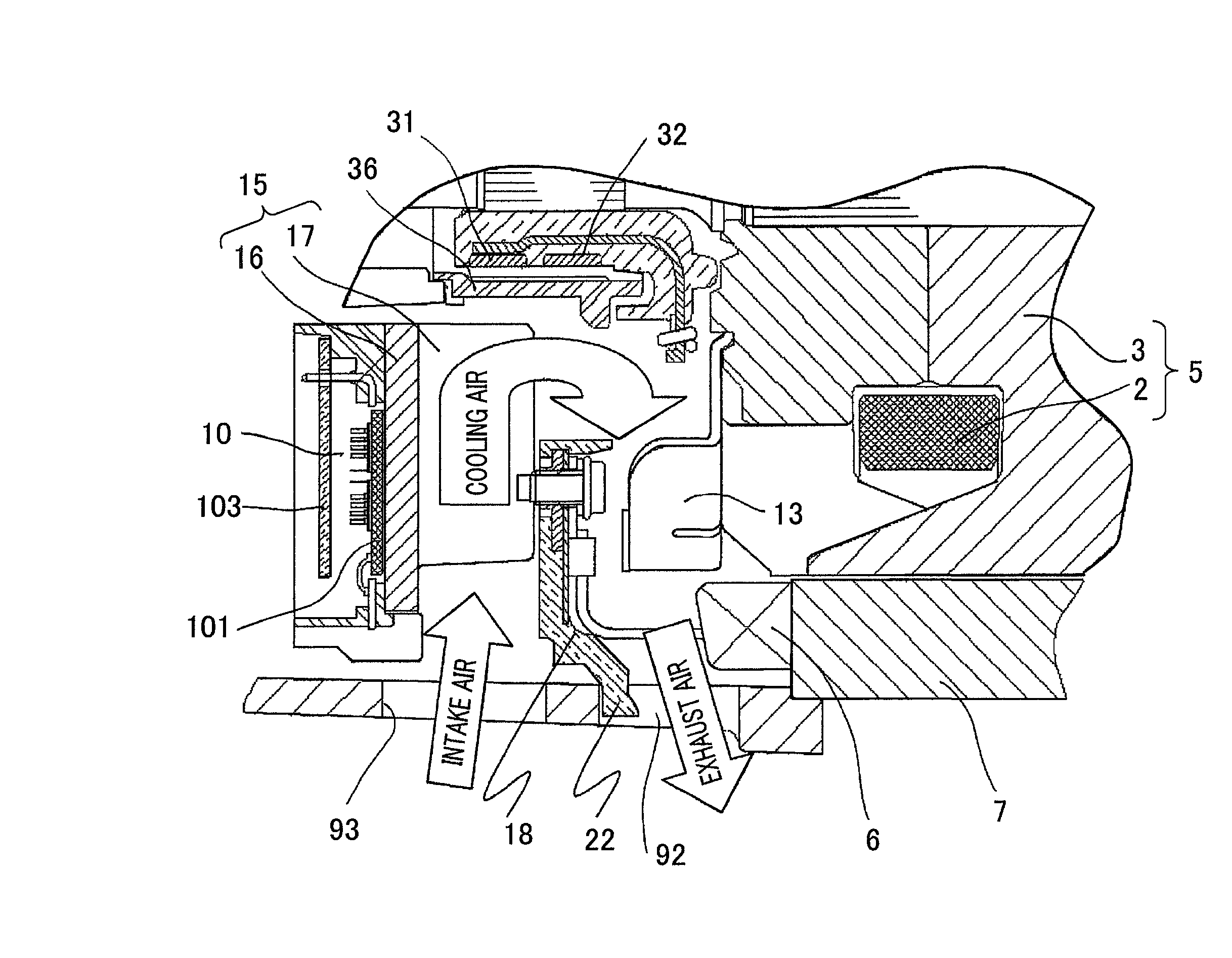
[0057]FIG. 7 is a cross-sectional view of principal parts of an electric rotating machine according to Embodiment 3. In Embodiment 3, in order to prevent exhausted cooling air from going toward an air inlet 93 in a rear-side housing 9, an exhausting guide 22 is formed in the peripheral portion of an intermediate plate 18. As a result, it can be prevented that air that has once passed through the electric rotating machine and has been warmed is absorbed again through the air inlet 93; therefore, cooling by the heat sink can effectively be performed.


PUM


Abstract

The electric rotating machine is provided with an intermediate plate having a power circuit connection portion that is connected with an outgoing lead drawn out from a power circuit unit and an armature winding connection portion that is connected with the power circuit connection portion and an outgoing lead drawn out from an armature winding. The power circuit connection portion and the armature winding connection portion are arranged at desired positions and outgoing leads from the armature winding of the stator are drawn out in such a way as to fall within a given space, so that intermediate connection lines for connecting windings can be shortened. Accordingly, not only the breakage of an intermediate connection line caused by a vibration can be prevented, but also the switching elements can separately be arranged so as to reduce thermal interference between the switching elements; therefore, the switching elements can effectively be cooled.

Description

BACKGROUND OF THE INVENTION[0001]1. Field of the Invention[0002]The present invention relates to an electric rotating machine, for a vehicle or the like, that is coupled with an engine, and particularly to the structure thereof.[0003]2. Description of the Related Art[0004]To date, there has been disclosed an in-vehicle AC generator in which there are formed two slots for each polarity and each phase in a stator iron core configured of laminated magnetic thin plates, and a set of U-phase, V-phase, and W-phase windings is configured with phase windings formed of coil conductors inserted in the slots (e.g., refer to Japanese Patent Application Laid-Open No. 2002-354736).[0005]In a conventional in-vehicle AC generator disclosed in Japanese Patent Application Laid-Open No. 2002-354736, a set of U-phase, V-phase, and W-phase windings is formed by connecting in series respective phase windings whose phases are different from one another by an electric angle of 30° by means of outgoing lead...

Claims


Application Information

Patent Timeline
Patent Type & Authority Patents(United States)
IPC IPC(8): H02K9/02
CPCH02K11/046H02K5/20H02K2203/09H02K5/207H02K11/05
Inventor MAEDA, NAOHIDEFUJITA, MASAHIKOKATO, MASAKI
Owner MITSUBISHI ELECTRIC CORP
Why Eureka
Try Eureka