
Anisotropic optical device with varying local imagewise and method for making same

an optical device and local image technology, applied in the direction of static indicating devices, instruments, polarising elements, etc., can solve the problems of not easily able to combine colourshift effects and well separated control of images, and achieve clear colour changes

Active Publication Date: 2012-02-07
ROLIC AG
View PDF15 Cites 17 Cited by
  • Summary
  • Abstract
  • Description
  • Claims
  • Application Information

AI Technical Summary

Benefits of technology

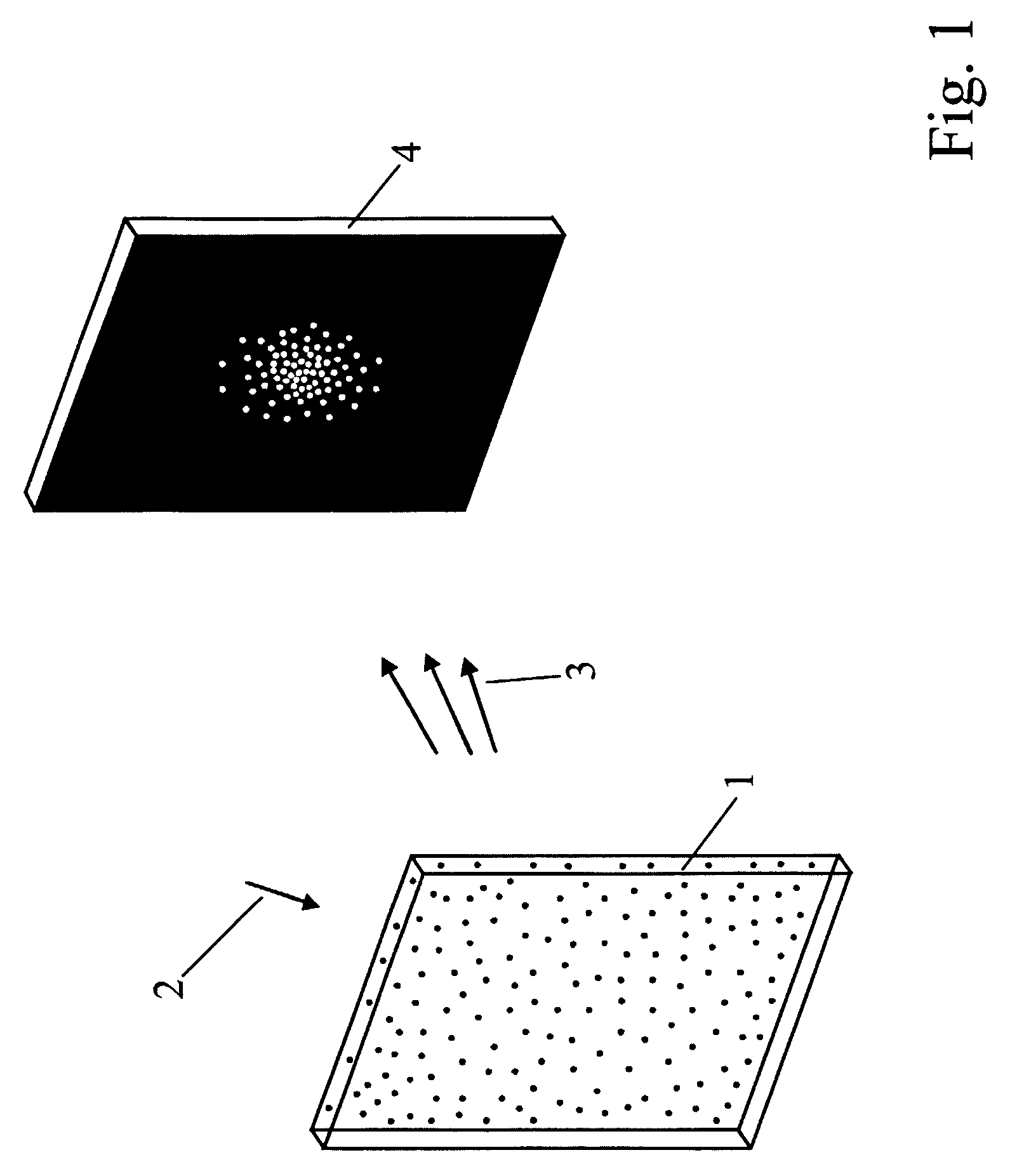
[0009]In contrast to the well-known holographic structures, an anisotropic diffuser shows very clear and distinct image flipping upon changing of the viewing angle. It however does not easily allow the combination with colourshift effects. The proposed combination of an anisotropic diffuser with distinct means for providing a well controlled colourshift provides the possibility of a superposition of distinct image flipping with well controlled and uniform colourshift. Since when using holographic structures a possible image flipping is always accompanied by concomitant colourshifts (often perceived as rainbow effects), the provision of a holographic structure with an additional mean for providing a colourshift will not lead to a well separated control of the image flipping and the colour flipping. Surprisingly however, the presently proposed combination of an anisotropic diffuser with patterned anisotropy with means for providing a colourshift allows a much clearer combination of image flipping and colourshift. Since the two effects are better separated than if instead of the anisotropic diffuser a periodic holographic structure is used, the two effects can be efficiently controlled and for example can be matched with each other. The for example possible specific coordination of the image flipping with the colourshift allows a surprising increase in the achievable security level of the devices in that for example a first image appear as under a first viewing angle in a first colour, and upon changing viewing angle almost without transmitional effects there appears the second image different from the first one in the second colour.
[0013]According to another preferred embodiment of the present invention, the means for providing a colourshift comprise an interference film or coating. The interference film or coating may comprise a multi-layer thin-film system based on dielectric materials, wherein the dielectric materials in different layers have different index of refraction. The interference film or coating may also represent a Fabry-Perot-resonator. In the latter case, the interference film or coating may comprise at least one partially transparent first metal film, and a second metal film and between those metal films a preferentially dielectric layer. The use of such a Fabry-Perot-resonator allows a particularly compact and efficient integrated structure, in that the anisotropic diffuser with patterned anisotropy is provided on a substrate, in that said anisotropic diffuser with patterned anisotropy comprises a topologically structured corrugated surface structure which is covered by a reflection metal layer, and in that seen from the viewing direction said anisotropic diffuser is directly covered by the dielectric layer of the Fabry-Perot-resonator.
[0020]Alternatively, it is possible to make a topologically structured corrugated surface structure as an anisotropic diffuser with patterned anisotropy by ultraviolet casting or hot embossing using a three-dimensionally structured stamper.

Problems solved by technology

It however does not easily allow the combination with colourshift effects.
Since when using holographic structures a possible image flipping is always accompanied by concomitant colourshifts (often perceived as rainbow effects), the provision of a holographic structure with an additional mean for providing a colourshift will not lead to a well separated control of the image flipping and the colour flipping.

Method used


Image

  • Anisotropic optical device with varying local imagewise and method for making same
  • Anisotropic optical device with varying local imagewise and method for making same
  • Anisotropic optical device with varying local imagewise and method for making same

Examples


specific examples

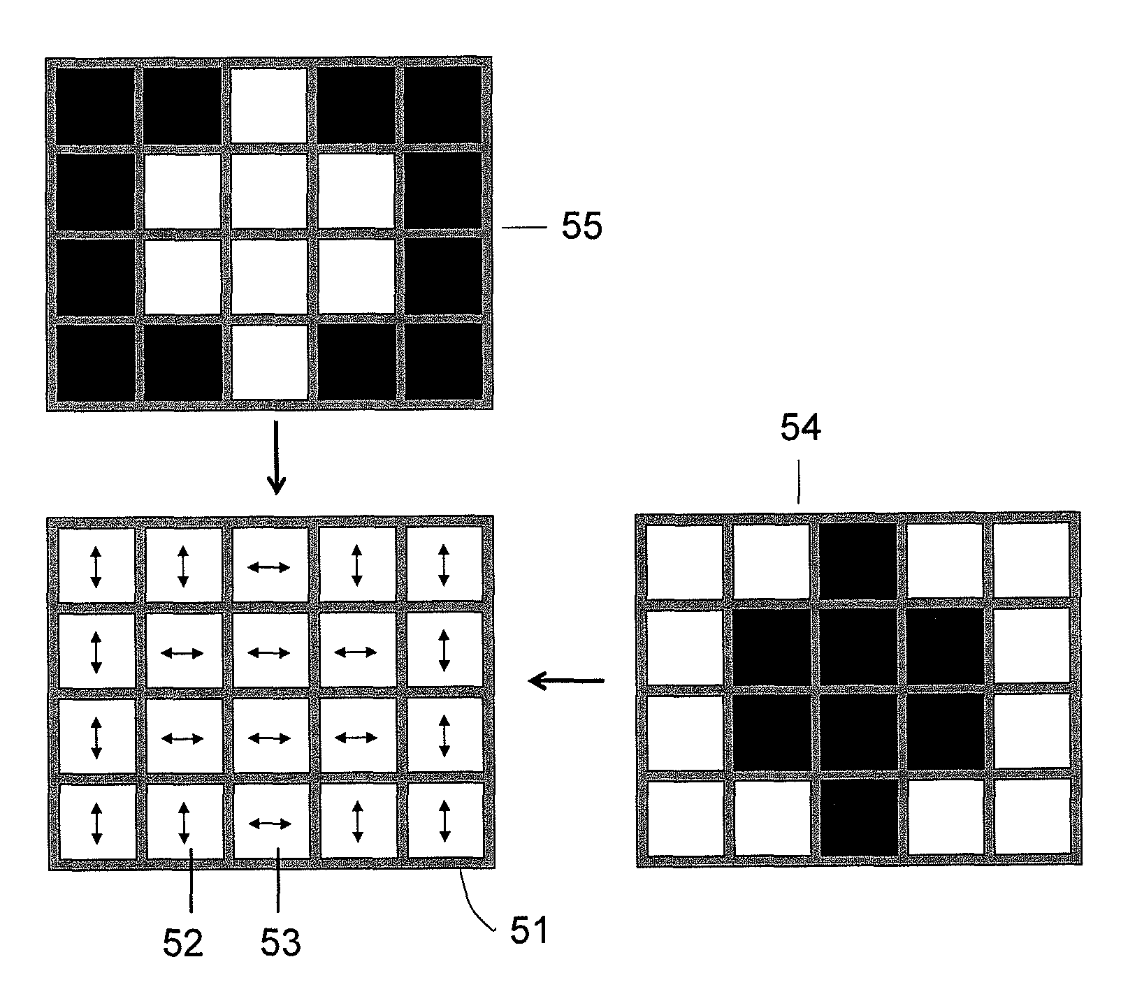
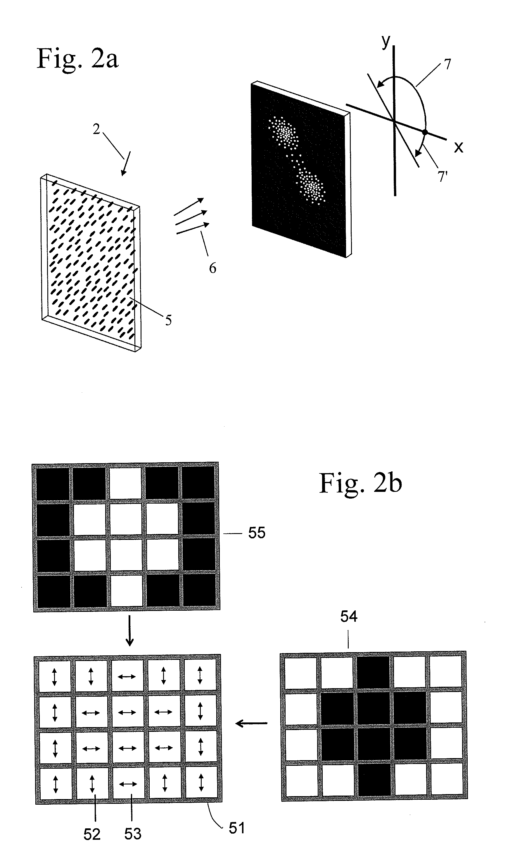
[0101]For all listed examples, which will be described in more detail, anisotropic scattering patterns according to FIG. 15 have been used (two differing anisotropy orientations). With the use of one patterned chromium mask, security devices with graphical illustrations, rastered grey scales and high resolution images (pictures) have been obtained. The pixel size is around 20 micrometers but could be made larger as well as even smaller (<10 micrometers).

example 1

[0102]A first example has been fabricated according to FIG. 3. As interference layer 11, a specially made three-layer Fabry-Perot reflector or an interference filter commercially available from Edmund Industrial Optics with a red reflection was used. Onto the interference layer 11 an anisotropic scattering film 10 was coated according to the film preparation described in WO-A-01 / 29148. As a photoalignment material, the material ROP103 from Rolic Technologies was used and coated with a film thickness of 30 to 60 nanometers by spin coating or by kbar coating. This film was exposed to UV light of a mercury vapor lamp of 1000 Watt in a Karl Suess housing and delivering about 3 mW / cm2 of 305 nm linearly polarised UV light. The UV light was polarised with a Moxtek (US) linear polariser. The first UV exposure also involved a masking of the photoalignment layer with a patterned chromium mask. The first exposure with linearly polarised UV light was carried out at with azimuthal orientation α...

example 2

[0106]A second example has been fabricated according to FIG. 6. In this case the anisotropic scattering film 10 is part of the interference film and therefore partly metallised 14. In a first step, a substrate 12 was metallised with aluminum by DC sputtering leading to the layer 9. The sputtering took place at an Argon flow of about 80 ml / min and a DC power of 300 W. The sample had a distance of 90 mm from the aluminum sputter target. The exposure time was 120 s. It resulted a highly reflecting aluminum film 9 for the visible wavelength range.

[0107]Then, a thin-film of a crosslinkable material was coated onto the metal reflector. In the present case a 15% diacrylate solution of butandiol-diacrylate (BDDA) in cyclopentanone was used. The solution was doped with 1% of BHT (Butylated Hydroxytoluene, also called 2,6,-di-(t-butyl)-4-hydroxytoluene) and 1% of the photoinitator Irgacure 369 of Ciba SC (CH). Again the film can be deposited by spin coating or kbar coating. The thickness of t...


PUM

PropertyMeasurementUnit
depthaaaaaaaaaa
depthaaaaaaaaaa
orientation angleaaaaaaaaaa

Abstract

The present invention relates to a new optical component comprising an anisotropic diffuser (5,10) with patterned anisotropy; and means (9, 11, 14, 16, 17, 20, 21, 30, 32) for providing a colorshift observable upon changing viewing angle (6) and / or changing angle of incident light (2). It also relates to methods for making such an optical component and uses of such optical components as security elements with a very high level of security.

Description

TECHNICAL FIELD[0001]The present invention relates to anisotropic optical devices and methods for making such devices. The proposed devices can be used in the field of optical security devices and the like.BACKGROUND OF THE INVENTION[0002]Due to further increased fraud and counterfeit of products and documents novel anticounterfeit measures are required more than ever. For many years holograms have been the preferred security-technology and many different generations of hologram-based security features have been fabricated. Meanwhile, this technology is more than 30 years old and therefore well known and widespread. This situation represents a security risk since many people have access to the hologram technology. With the availability of digital hologram printers, the path to easy to use holographic mastering systems have further increased. These printers allow the production of many different types of holograms and a minimal knowledge of holographic set-ups or laser writers is req...

Claims


Application Information

Patent Timeline
Patent Type & Authority Patents(United States)
IPC IPC(8): G02F1/1335G09G3/36G02B5/02G02B5/28G02B5/30G02F1/1337G06K19/14
CPCG02B5/0257G02B5/28G02B5/3016G02B5/0284B42D2033/26Y10T428/21G02B5/286B42D25/355B42D25/364B42D25/324G02B5/30G02F1/1337
Inventor STALDER, MARTINIBN-ELHAJ, MOHAMMEDMOIA, FRANCO
Owner ROLIC AG
Learn More