Robust six degree-of-freedom micromachined gyroscope with anti-phase drive scheme and method of operation of the same

a micro-machined gyroscope and anti-phase technology, applied in the direction of acceleration measurement using interia force, acceleration measurement in multiple dimensions, instruments, etc., can solve the problems of adding complexity to the system, unable to maintain precise anti-phase motion in both the drive and the sense directions, and the device can indeed reject, etc., to achieve the effect of effective or substantially rejecting common-mode stimuli

Active Publication Date: 2012-02-14
RGT UNIV OF CALIFORNIA
View PDF7 Cites 86 Cited by
  • Summary
  • Abstract
  • Description
  • Claims
  • Application Information

AI Technical Summary

Benefits of technology

[0009]The illustrated embodiment of the invention introduces a multi-degree of freedom design approach to gyroscope devices that are driven in anti-phase for the passive relaxation of sense mode phase matching requirements. A six degree-of-freedom micromachined gyroscope with anti-phase drive for the measurement of angular rate is disclosed. The gyroscope is comprised of two three degree-of-freedom (3-DOF) subsystems coupled in the drive-mode and driven into anti-phase oscillation to effectively or substantially reject common-mode stimuli. Each of the 3-DOF subsystems contains two proof masses that form a 1-DOF drive oscillator and 2-DOF sense oscillator, mechanically decoupled via a decoupling frame. The two 1-DOF drive oscillators are connected together with a flexure, thus making the overall drive a 2-DOF coupled system. Directly coupling the two drive subsystems provides a common anti-phase drive-mode resonant frequency, at which the two gyroscopic subsystems naturally oscillate in opposite directions. The 2-DOF sense-mode oscillators of each gyroscopic subsystem provide a flat range in their frequency response, where the response gain and phase are stable. The gain and phase stability of this range leads to robustness to imperfections and environmental influences, and provides precise matching of sense-mode amplitude and phase of the two gyroscopic subsystems.
[0010]In the illustrated design, the flat frequency response ranges of each 2-DOF sense-mode oscillators are overlapped, and the anti-phase drive resonant frequency (at which the overall device is operated) is located within the overlapping flat ranges. The resulting six-degree of freedom dynamical system eliminates amplitude and phase stability problems of conventional tuning-fork micromachined gyroscopes to minimize bias and effectively reject common-mode stimuli.

Problems solved by technology

One drawback to such a device is that the motion of both the drive and sense masses must be precisely in anti-phase so that the device can indeed reject common mode stimuli.
In practice, due to inevitable imperfections in the mechanical structure, there are issues with maintaining precise anti-phase motion in both the drive and the sense directions.
Methods for achieving this motion in the drive direction have been proposed including device designs and control architectures that force anti-phase motion, but this adds complexity to the system.
Another problem that is often overlooked in tuning fork devices is maintaining the anti-phase response of the sense mode, specifically the potentially large phase variations that can occur when operating at or very near resonant frequencies.
However, the sensitivity of the device is sacrificed drastically when advantage of sense-mode resonance is not utilized.

Method used


Image

  • Robust six degree-of-freedom micromachined gyroscope with anti-phase drive scheme and method of operation of the same
  • Robust six degree-of-freedom micromachined gyroscope with anti-phase drive scheme and method of operation of the same
  • Robust six degree-of-freedom micromachined gyroscope with anti-phase drive scheme and method of operation of the same

Examples


Embodiment Construction

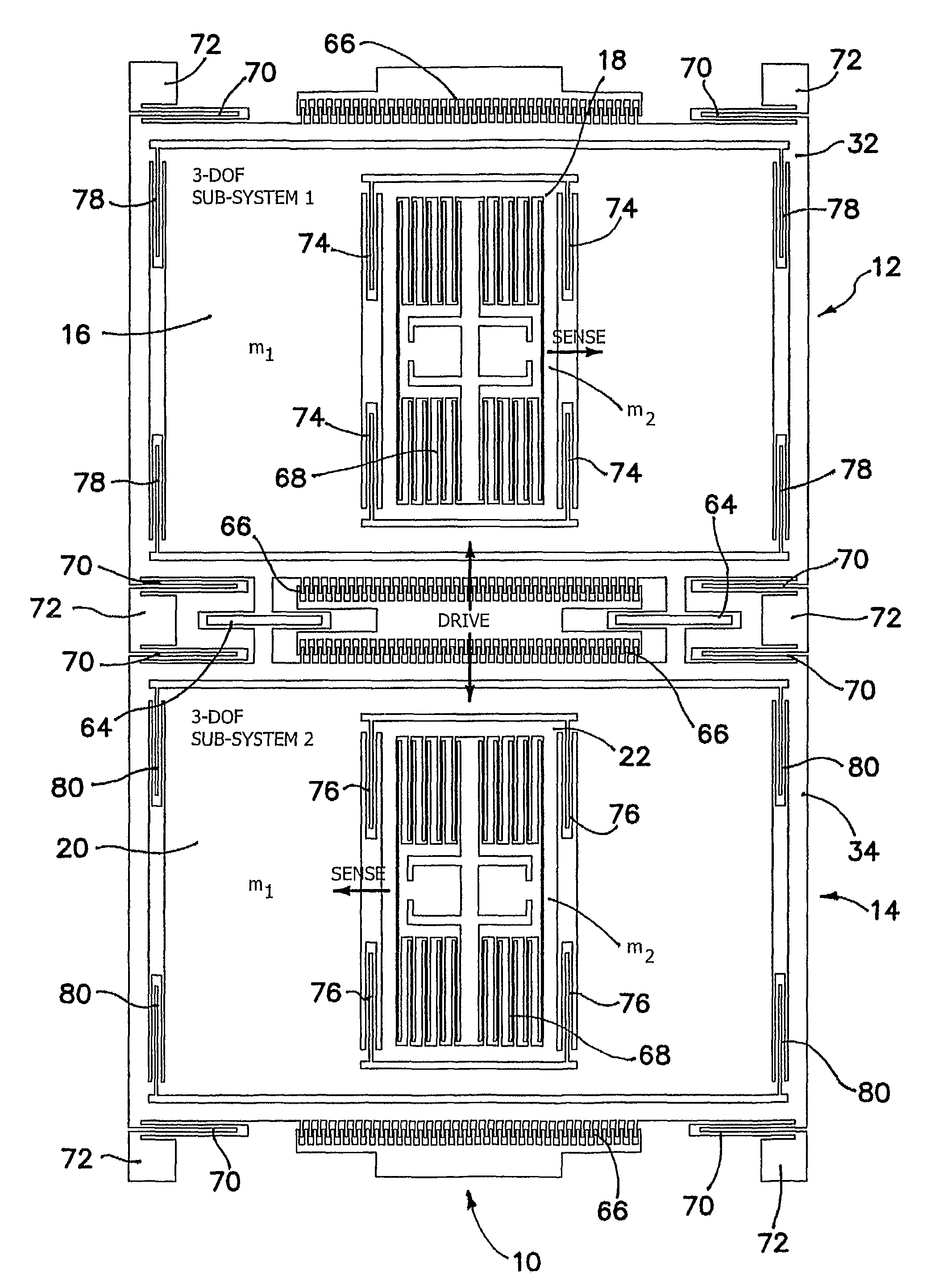
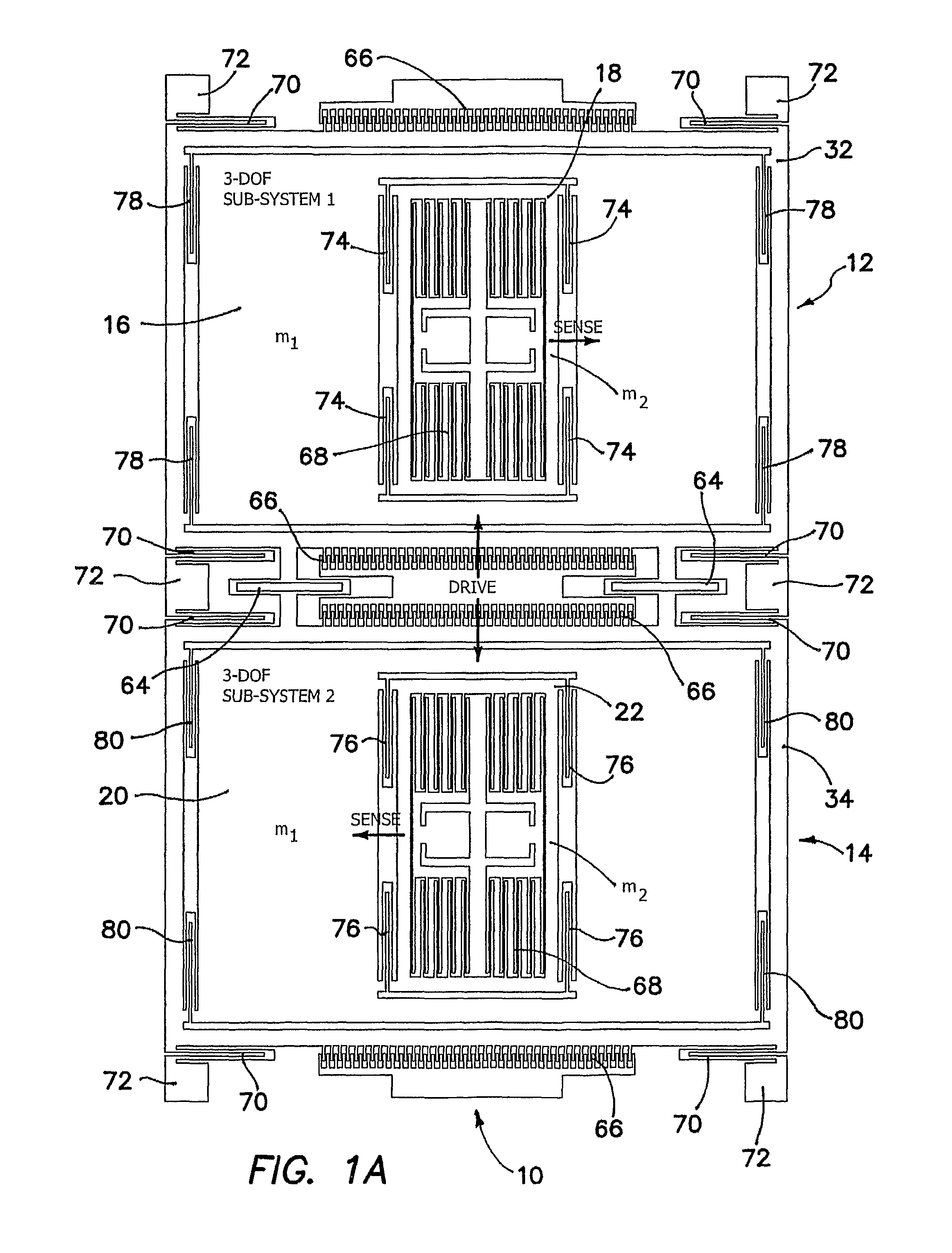
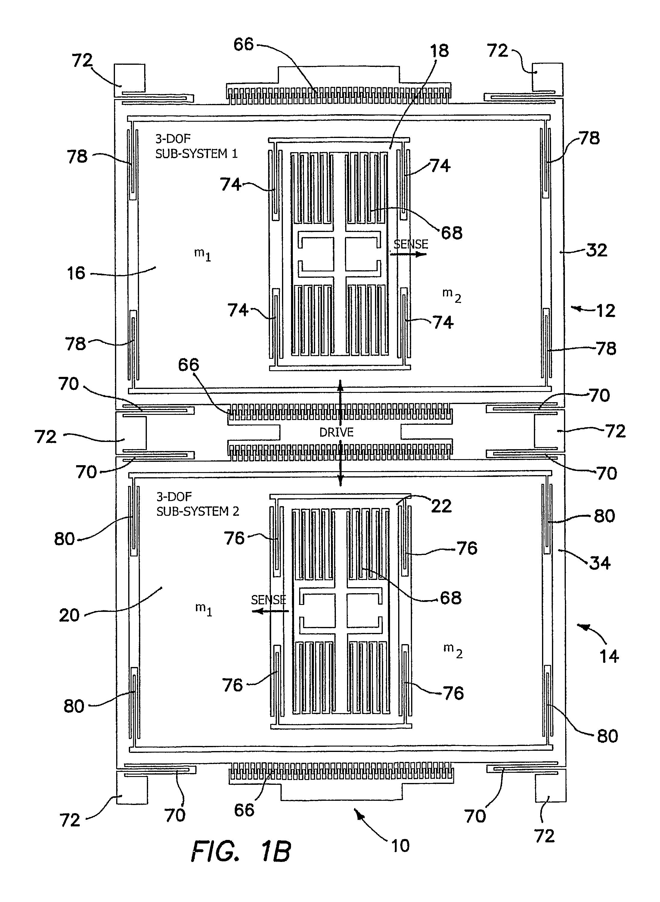
[0027]The problem to which the illustrated invention is addressed is the susceptibility of the sense-mode response amplitude and phase of conventional micromachined gyroscopes to environmental and fabrication variations. A conventional gyroscope is typically comprised of a mass (or masses) constrained to move in two modes: the drive and sense directions, assumed by convention to the x and y directions respectively in a planar coordinate reference frame. It is assumed that there is no motion in the direction orthogonal to these modes and thus has two degrees of freedom. The drive and sense modes are orthogonal to each other so that when the mass is driven by forced vibration, there should be no motion in the sense direction. The sense mode is excited by the sinusoidal Coriolis force induced in the presence of an angular rate orthogonal to both the drive and sense directions. The amount of the sense mode response is directly related to the drive velocity, the input angular rate, and t...


PUM


Abstract

A method of operating an anti-phase six degree-of-freedom tuning fork gyroscope system comprises the steps of driving a first three degree-of-freedom gyroscope subsystem, and driving a second three degree-of freedom gyroscope subsystem in an anti-phase mode with the first gyroscope subsystem at an anti-phase resonant frequency. Acceleration or an angular rate of motion is sensed by the first and second three degree-of-freedom gyroscope subsystems operating in a flat frequency response range where the anti-phase resonant frequency is designed. Response gain and phase are stable and environmental and fabrication perturbations are avoided by such operation. A anti-phase six degree-of-freedom tuning fork gyroscope system which operates as described is also characterized.

Description

BACKGROUND OF THE INVENTION[0001]1. Field of the Invention[0002]The invention relates to the field of micromachined gyroscopes and accelerometers, and in particular to designs for anti-phase devices to compensate for fabrication and environmental variations.[0003]2. Description of the Prior Art[0004]In recent years, the development of microelectromechanical systems (MEMS) and the improvement of fabrication techniques have opened new avenues for the development of low-cost sensors. This is especially true for inertial sensors, more specifically micromachined gyroscopes which have shown enormous potential for a wide range of applications.[0005]When two masses are oscillating with a 180 degrees phase difference, they are considered to be moving in opposite directions. This type of motion is referred to as “anti-phase,” since they are oscillating out of phase with exact opposite motion paths. Typically, this technique is employed in the drive direction of vibratory gyroscopic devices wh...

Claims


Application Information

Patent Timeline
Patent Type & Authority Patents(United States)
IPC IPC(8): G01C19/00
CPCG01C19/574G01P15/18G01P15/14Y10T74/1225
Inventor ACAR, CENKSHKEL, ANDREISCHOFIELD, ADAM R.COSTLOW, LYNN E.MADNI, ASAD M.
Owner RGT UNIV OF CALIFORNIA
Why Eureka
Try Eureka