Crystalline colloidal array deep UV narrow band radiation filter

a radiation filter and colloidal array technology, applied in the direction of optical radiation measurement, instruments, spectrometry/spectrophotometry/monochromators, etc., can solve the problems of inability to operate in the deep, inability to absorb uv non-absorption materials, and inability to readily be found in the uv region, etc., to achieve the effect of rejecting

Inactive Publication Date: 2012-03-15
ASHER SANFORD A
View PDF11 Cites 4 Cited by
  • Summary
  • Abstract
  • Description
  • Claims
  • Application Information

AI Technical Summary

Benefits of technology

[0013]These and other needs are satisfied by various aspects of the invention which provide highly charged monodisperse, UV substantially transparent particles, methods of making highly charged monodisperse, UV substantially transparent particles, methods of making CCA deep UV narrow band radiation filters from the particles, and hyperspectral imaging devices. The CCA deep UV narrow band filters can selectively and effectively reject a narrow band of wavelengths from a broader spectrum of incident radiation while transmitting adjacent wavelengths to a high degree.

Problems solved by technology

The widely used holographic filters cannot operate in the deep UV region because the materials contained in these filters strongly absorb deep UV light.
In principle, dielectric interference filters could exist in the deep UV but the necessary deep UV nonabsorbing materials are not readily available and the fabrication process is expensive and complicated.
A subtractive dispersion double monochromator could be used as a tunable filter to block specific spectral ranges, but these devices are mechanically complex, large and expensive.
However, no deep UV CCA filter presently exists due to the lack of appropriate colloidal particles; deep UV operation of CCA filters requires monodisperse and highly charged CCA particles that do not absorb deep UV light.
Few materials permit high transmittance in the deep UV and can be used for the UV optical applications.
None of the above compounds would work as substantially deep UV transparent particles because their compositions contain components which strongly absorb in the deep UV spectrum.

Method used


Image

  • Crystalline colloidal array deep UV narrow band radiation filter
  • Crystalline colloidal array deep UV narrow band radiation filter
  • Crystalline colloidal array deep UV narrow band radiation filter

Examples


example 1

[0052]Charged silica particles were formed by attaching a high surface density of non UV light absorbing silane coupling agent (3-(trihydroxylsilyl)-1-propane-sulfonic acid, THOPS) to the surface of the small silica particles. A typical reaction used 5 mL tetraethoxysilane (TEOS, Fluka, Lot code 1332815 41207016) as the silica precursor, 8 mL ammonium hydroxide (29.40 wt %, J. T. Baker) as the catalyst, and 200 mL ethanol as the reaction solvent. The reaction mixture was stirred for 24 h. The resulting silica dispersion was filtered through a nylon mesh with 100 micron pore size. 200 mL of water was slowly added to the silica dispersion while stirring. The mixture was first heated to 50° C. for ˜30 min, then heated to 80° C. for ˜1 h. 6 mL of the silane coupling agent (3-(trihydroxylsilyl)-1-propane-sulfonic acid, THOPS, 30-35% in water, Gelest, Inc.) was adjusted to pH ˜6 by adding ammonium hydroxide and then added to the silica dispersion. The reaction was refluxed for 6 h at 80° ...

example 2

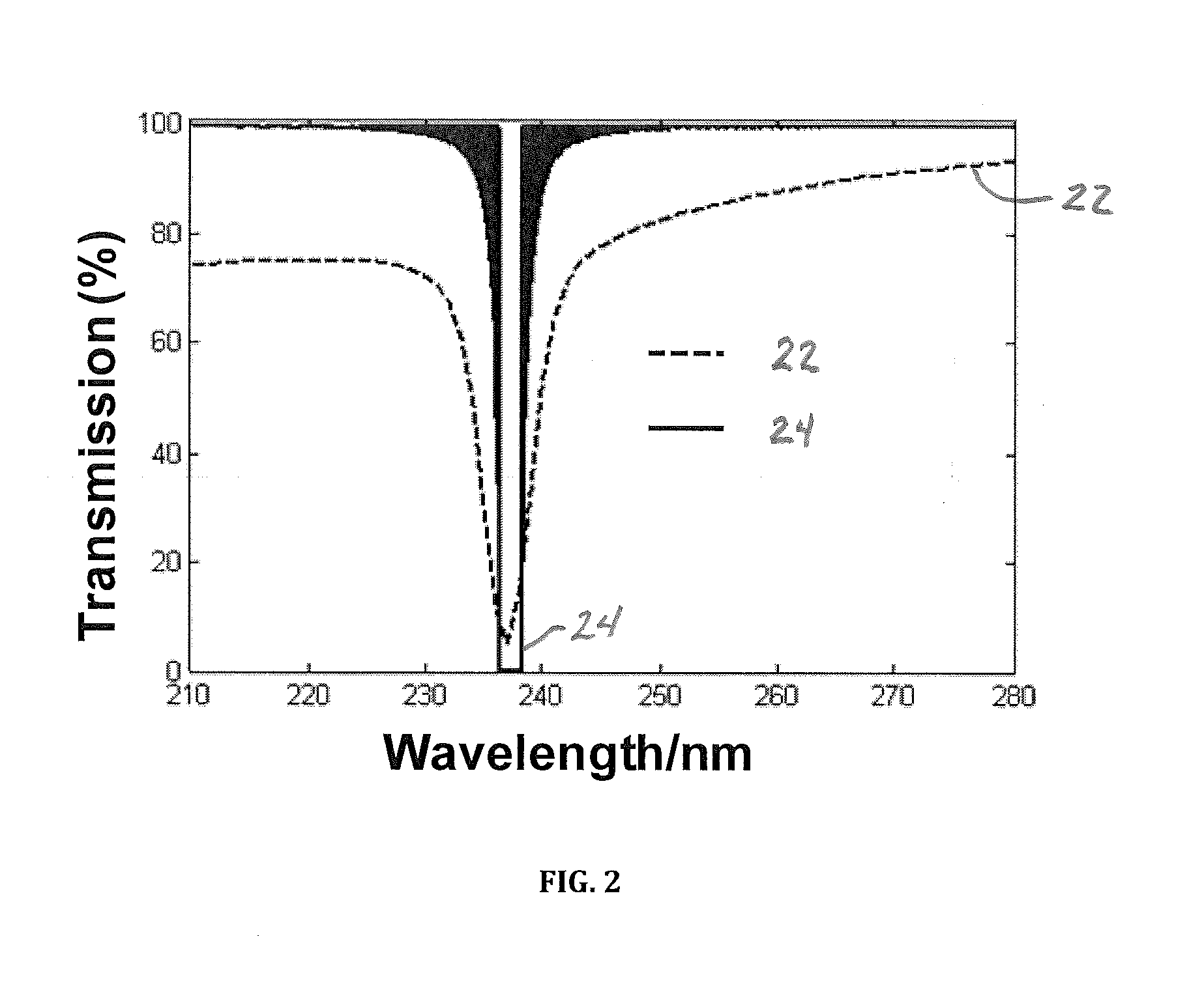
[0053]The Bragg diffracted wavelength of the CCA filter made from the highly charged silica particles (volume percentage 7.0%) from Example 1 can be easily tuned by changing the incident light glancing angle. FIG. 4 illustrates transmission spectra of the highly charged silica CCA filter for incident glancing angles of 90°, 69° and 66°. The band rejection wavelength can be easily tuned from 237 nm to 227 nm by tilting the filter with respect to the incident beam as shown in FIG. 4. The full bandwidth, indicated by these measurements, is 6 nm to the 50% transmittance points and 1 nm to the 15% transmittance points for normal incidence. This measured full bandwidth is broader than the true CCA bandwidth because the absorption spectrophotometer used has a weakly focused sampling beam. The full bandwidth to the 50% transmission points determined by a Teflon Raman measurement is only 4 nm. For a Rayleigh rejection filter, only half full bandwidth is involved in the long wavelength pass f...

example 3

[0054]The highly charged silica CCA filter from Example 2 can be used to reject Rayleigh scattered light in UV Raman spectral measurements. A Teflon film was used as the sample for the Raman measurements. Raman spectra were excited with the 229 nm line (2 mW) from a continuous-wave UV Ar laser (Innova 300 FReD, Coherent Inc.). The schematic of the triple-stage monochromator and the CCA filter for Raman measurements for one embodiment is shown in FIG. 5. The spectrometer premonochromator 28 (illustrated as a double monochromator) having a bandpass slit 30 and gratings 32) was aligned to block most of the Rayleigh scattered light to avoid saturating the CCD camera 34. The embodiment shown has an entrance slit 36 and additional gratings 38. All optical elements of the spectrometer were identical for Raman spectra measured in the absence and presence of the CCA filter 40. The CCA filter 40 was placed between a collection 42 and imaging lens 44 where the light is collimated. Raman spectr...


PUM

PropertyMeasurementUnit
diameteraaaaaaaaaa
diameteraaaaaaaaaa
wavelengthaaaaaaaaaa

Abstract

The present invention provides a method of making highly charged, monodisperse particles which do not absorb deep ultraviolet (UV) light and a method of making crystalline colloidal array (CCA) deep UV narrow band radiation filters by using these highly charged monodisperse particles. The CCA filter rejects and / or selects particular regions of the electromagnetic spectrum while transmitting adjacent spectral regions. The filtering devices of the present invention are wavelength tunable over significant spectral intervals by changing the incident angle of the CCA filter relative to the light. Larger wavelength changes can be obtained by changing the concentrations of particles in the CCAs. The present invention also includes applications of the CCA filter to hyperspectral imaging and Raman imaging devices.

Description

CROSS-REFERENCE TO RELATED APPLICATIONS[0001]This application claims the benefit of provisional patent application Ser. No. 61 / 382,551 filed 2010 Sep. 14 by the present inventors.FEDERALLY SPONSORED RESEARCH[0002]The invention described herein was made with government support under Contract No. 1R01EB009089 awarded by the National Institute of Health. Therefore, the government has certain rights in the invention.BACKGROUNDPrior Art[0003]Optical spectroscopy plays an important role in chemical analysis, materials science and in static and dynamic studies of biological structure. Many applications require wavelength-selective optical elements to reject and / or select particular regions of the electromagnetic spectrum while transmitting adjacent spectral regions. Typical examples include fluorescence measurements, Raman spectroscopy and the many pump-probe techniques. These pump-probe techniques excite a sample at a particular wavelength and probe at other wavelengths to monitor absorpt...

Claims


Application Information

Patent Timeline
Patent Type & Authority Applications(United States)
IPC IPC(8): G01J3/44G01J3/28G02B5/20C07F7/18C08G77/28
CPCC08G77/28G01J3/32G02B5/208G01J2003/1213G01J3/44
Inventor ASHER, SANFORD A.WANG, LULINGTUSCHEL, DAVID
Owner ASHER SANFORD A
Why Eureka
Try Eureka