Non-pneumatic tire

a non-pneumatic, tire technology, applied in the direction of tyre parts, wheel attachments, transportation and packaging, etc., can solve the problems of adverse effect of ground pressure dispersion, noise and the like, and insufficient effect of suppressing the buckling of the ground portion between the web spokes, etc., to achieve the effect of improving rigidity fluctuation and ground pressure, and suppressing the buckling of the ground portion

Active Publication Date: 2012-02-14
TOYO TIRE & RUBBER CO LTD
View PDF19 Cites 51 Cited by
  • Summary
  • Abstract
  • Description
  • Claims
  • Application Information

AI Technical Summary

Benefits of technology

[0013]Accordingly, an object of the present invention is to provide a non-pneumatic tire which can improve a riding quality, a noise performance and the like while improving a durability, and can further sufficiently suppress a buckling of a ground portion between spokes, because a circumferential fluctuation of a tire rigidity is hard to be generated due to a positional relationship between a spoke position and a center position of the ground surface, and a strain can be dispersed into each of portions of a support structure body.
[0019]Since the non-pneumatic tire according to the present invention is provided with the intermediate annular portion, it is possible to burden the intermediate annular portion with the deformation (the strain) concentrated in the outer coupling portion, at the time when the position of the coupling portion between the outer coupling portion and the outer annular portion is grounded, and it is possible to uniformize the deformation of the support structure body. As a result, in the non-pneumatic tire according to the present invention, the circumferential fluctuation of the tire rigidity is hard to be generated by the positional relationship between the position of the outer coupling portion (the spoke) and the center position of the ground surface, and it is possible to suppress the buckling of the ground portion between the outer coupling portions. In addition, since the number of the outer coupling portions is larger than the number of the inner coupling portions, the interval between the adjacent outer coupling portions becomes narrow, and it is possible to further suppress the buckling of the ground portion between the outer coupling portions.
[0020]In the non-pneumatic tire according to the present invention, it is preferable that the outer coupling portion is inclined with respect to the tire diametrical direction. Since the outer coupling portion is inclined with respect to the tire diametrical direction, it is possible to burden the intermediate annular portion with the deflection of the outer coupling portion in comparison with the case where the outer coupling portion is the same as the tire diametrical direction, at the time when the position of the coupling portion between the outer coupling portion and the outer annular portion is grounded, and it is possible to uniformize the deformation of the support structure body. As a result, the circumferential fluctuation of the tire rigidity is hard to be generated by the positional relationship between the position of the outer coupling portion and the center position of the ground surface, and it is possible to improve the noise caused by a rolling motion and the riding quality.
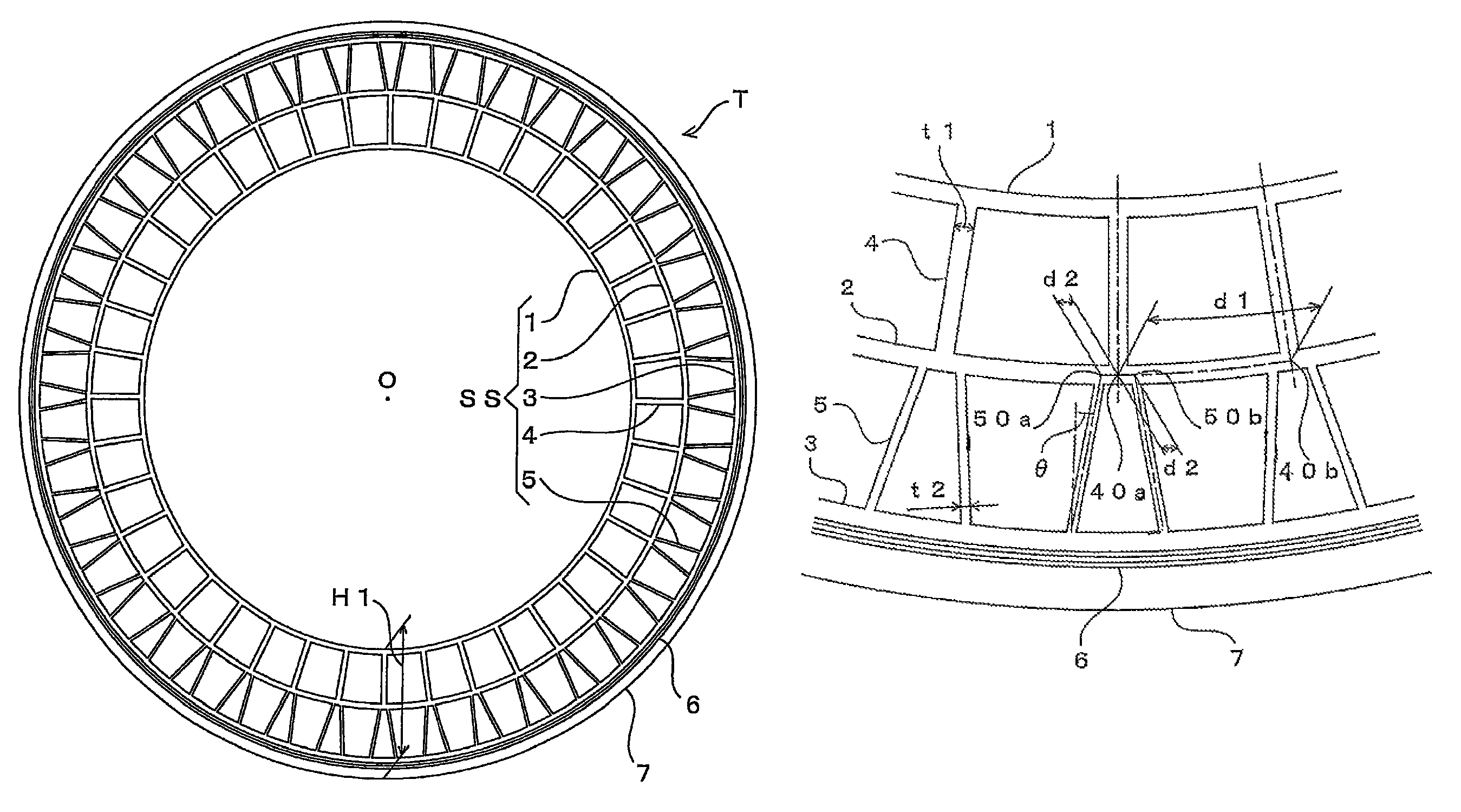
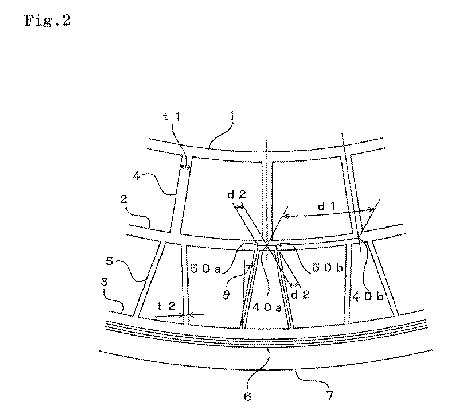
[0021]In the non-pneumatic tire according to the present invention, it is preferable that the two outer coupling portions inclined in a direction which is symmetrical with respect to a tire diametrical direction, and the one inner coupling portion along the tire diametrical direction are arranged in a Y-shaped form as seen from a tire axial direction. Since two outer coupling portions and one inner coupling portion are arranged in the Y-shaped form, the coupling portion between the outer coupling portion and the intermediate annular portion comes close to the coupling portion between the inner coupling portion and the intermediate annular portion. Accordingly, it is possible to burden the intermediate annular portion with the deflection of the outer coupling portion accurately. Therefore, it is possible to improve the circumferential fluctuation of the tire rigidity, the suppression of the buckling, and the performances such as the durability, the rolling resistance and the like. Further, since the coupling portion between the outer coupling portion and the intermediate annular portion comes close to the coupling portion between the inner coupling portion and the intermediate annular portion, the tensile forces tend to be transmitted from each other, and the load supporting performance is increased.
[0022]In the non-pneumatic tire according to the present invention, it is preferable that a thickness of the outer coupling portion is less than a thickness of the inner coupling portion. It is possible to reduce the compression rigidity by making the thickness of the outer coupling portion smaller than the thickness of the inner coupling portion, and it is possible to well suppress the circumferential fluctuation of the tire rigidity. In the present invention, since the number of the outer coupling portions is larger than the number of the inner coupling portions, the compression rigidity of the outer coupling portion is too high if the thickness of the outer coupling portion is equal to or larger than the thickness of the inner coupling portion, so that there is a risk that the suppressing effect of the circumferential fluctuation of the tire rigidity is lowered.
[0023]In the non-pneumatic tire according to the present invention, it is preferable that a gap is provided between an outer coupling point at which one of the two outer coupling portions and the intermediate annular portion are coupled, and an outer coupling point at which the other of the outer coupling portions and the intermediate annular portion are coupled. In the case where two outer coupling portions and one inner coupling portion are arranged in the Y-shaped form as seen from the tire axial direction, the compression force of the inner coupling portion is hard to be directly transmitted to the outer coupling portion by setting the gap between the outer coupling point at which one outer coupling portion and the intermediate annular portion are coupled, and the outer coupling point at which the other outer coupling portion and the intermediate annular portion are coupled, whereby it is possible to prevent the strain in the outer coupling portion from being enlarged. Further, it is possible to burden the intermediate annular portion between two outer coupling points with the tensile force of the inner coupling portion and the outer coupling portion, by setting the gap therebetween. Further, it is assumed that the outer coupling point is a point at which a thickness center line of the outer coupling portion intersects a thickness center line of the intermediate annular portion.

Problems solved by technology

However, it has been known that the non-pneumatic tire described in Japanese Patent No. 3966895 has a similar structure to the non-pneumatic tire described in Japanese Unexamined Patent Publication No. 2005-500932, in the individual zone, and is not sufficient in an effect of suppressing the buckling of the ground portion between the web spokes.
Further, in the non-pneumatic tire described in Japanese Patent Unexamined Publication No. 1-314602, since the web extending in a radial direction is arranged in the center portion in the width direction of the rib over the tire circumference, the compression rigidity becomes too high, and an adverse effect is given to a ground pressure dispersion, a riding quality, a noise and the like.
Further, since the load is directly transmitted to the ground surface structurally in the ground side, it is impossible to expect an improvement in rigidity fluctuation and the ground pressure dispersion.

Method used


Image

  • Non-pneumatic tire
  • Non-pneumatic tire
  • Non-pneumatic tire

Examples


example 1

[0090]The above-mentioned performance was evaluated by preparing a non-pneumatic tire having the support structure body provided with the inner ring (corresponding to the inner annular portion 1), the intermediate ring (corresponding to the intermediate annular portion 2), the outer ring (corresponding to the outer annular portion 3), the inner spoke (corresponding to the inner coupling portion 4), and the outer spoke (corresponding to the outer coupling portion 5), three layers of reinforcing layers provided in the outer periphery thereof, and the tread rubber, in accordance with dimensions, physical properties and the like shown in Table 1. In the example 1, the inner coupling portion 4 and the outer coupling portion 5 were arranged as shown in FIG. 3. In other words, the outer coupling portion 5 was arranged in such a manner that no gap is provided between the outer coupling point 50a and the outer coupling point 50b. Result of the rigidity fluctuation test is shown in FIG. 5. Re...

example 2

[0091]In the same manner as the example 1, the above-mentioned performance was evaluated by forming the support structure body provided with the inner ring, the intermediate ring, the outer ring, the inner spoke, and the outer spoke, and preparing the non-pneumatic tire having three layers of reinforcing layers provided in the outer periphery thereof, and the tread rubber, in accordance with dimensions, physical properties and the like shown in Table 1. In the example 2, the inner coupling portion 4 and the outer coupling portion 5 were arranged as shown in FIG. 2. In other words, the outer coupling portion 5 was arranged in such a manner that a gap is provided between the outer coupling point 50a and the outer coupling point 50b. Result of the rigidity fluctuation test is shown in FIG. 5. Results of the maximum ground pressure and the variance of the ground pressure are shown together in Table 1.


PUM


Abstract

The invention provides a non-pneumatic tire which can improve a riding quality, a noise performance and the like while improving a durability, and can further sufficiently suppress a buckling of a ground portion between spokes, because a circumferential fluctuation of a tire rigidity is hard to be generated due to a positional relationship between a spoke position and a center position of the ground surface, and a strain can be dispersed into each of portions of a support structure body. In a non-pneumatic tire T comprising a support structure body SS supporting a load from a vehicle, the support structure body SS includes an inner annular portion 1, an intermediate annular portion 2 concentrically provided in an outer side of the inner annular portion 1, an outer annular portion 3 concentrically provided in an outer side of the intermediate annular portion 2, a plurality of inner coupling portions 4 coupling the inner annular portion 1 and the intermediate annular portion 2, and a plurality of outer coupling portions 5 coupling the outer annular portion 3 and the intermediate annular portion 2, and the number of the outer coupling portions 5 is larger than the number of the inner coupling portions 4.

Description

BACKGROUND OF THE INVENTION[0001]1. Field of the Invention[0002]The present invention relates to a non-pneumatic tire provided with a support structure body supporting a load from a vehicle, serving as a tire structure member, and preferably relates to a non-pneumatic tire which can be used in place of a pneumatic tire.[0003]2. Description of the Related Art[0004]A pneumatic tire has a function of supporting a load, a performance of absorbing a shock from a ground surface, and a performance of transmitting a power (accelerating, stopping and direction changing performance), and is accordingly employed in various vehicles, particularly a bicycle, a motor cycle, an automobile and a truck.[0005]Particularly, these capabilities greatly have contributed to a development of the automobile and other motor vehicles. Further, the shock absorbing performance of the pneumatic tire is useful in a transportation cart for medical equipment and an electronic device, and for other intended uses.[00...

Claims


Application Information

Patent Timeline
Patent Type & Authority Patents(United States)
IPC IPC(8): B60C7/00
CPCB60B9/10Y10T152/10297
Inventor ARAKAWA, KOJIIWASE, MASANORISEGAWA, MASAHIRO
Owner TOYO TIRE & RUBBER CO LTD
Why Eureka
Try Eureka