Pressure tank, an device for feeding powder to a conveying pipe, and its feeding method, and method for determining feeding intervals of powder to the conveying pipe

a pressure tank and conveying pipe technology, applied in the direction of conveyors, bulk conveyors, transportation and packaging, etc., can solve the problems of large, complicated apparatus structure, and high cost, and achieve the effect of simple and compact structure and lower cos

Active Publication Date: 2012-02-14
SINTOKOGIO LTD
View PDF16 Cites 82 Cited by
  • Summary
  • Abstract
  • Description
  • Claims
  • Application Information

AI Technical Summary

Benefits of technology

[0021]This invention was conceived to solve these problems. The first purpose of this invention is to provide a pressure tank that is used for an apparatus for intermittently feeding powder to a conveying pipe, and that has a simple structure. It is also to provide an apparatus and a method for feeding the powder to the conveying pipe by using the pressure tank.
[0098]Thus, compared to the conventional pressure tank, the tank of this invention has excellent advantages, such as its simple and compact structure and its lower cost.
[0114]Thus, the method of this invention has excellent advantages since the method can be adjusted so as to optimize the pressure of the compressed air in the conveying pipe by controlling the timing for operating the electromagnetic valves to intermittently supply a predetermined amount of the powder to the conveying pipe.

Problems solved by technology

However, in this conventional apparatus for feeding powder to a conveying pipe, there are problems, such as that the structure of the apparatus is complicated, large, and costly.

Method used


Image

  • Pressure tank, an device for feeding powder to a conveying pipe, and its feeding method, and method for determining feeding intervals of powder to the conveying pipe
  • Pressure tank, an device for feeding powder to a conveying pipe, and its feeding method, and method for determining feeding intervals of powder to the conveying pipe

Examples


Embodiment Construction

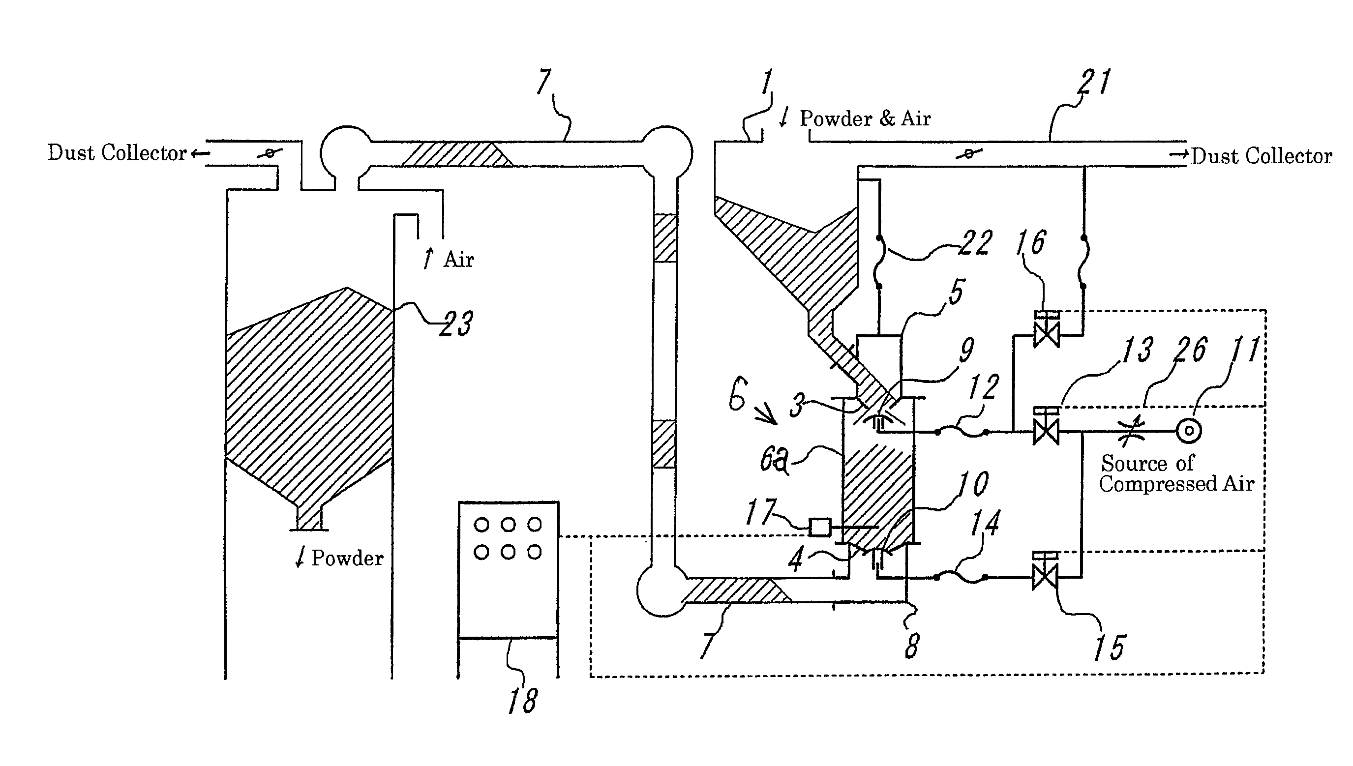
[0116]First, based on FIG. 1, the apparatus for feeding powder to a pipe is explained in detail.

[0117]The apparatus for intermittently feeding a predetermined amount of powder to a conveying pipe 7, which is used for the plug-conveying system that conveys powder by compressed air by means of a conveying pipe 7, has a pressure tank 6.

[0118]The pressure tank 6 is comprised of:

[0119]a tank body 6a that forms the structure of the pressure vessel, wherein the tank body 6a has a receiving port 3 at its upper portion and a discharging port 4 at its lower portion,

[0120]a first check valve 9 disposed just under the receiving port 3 so that it can freely move up and down, and so that it can close the receiving port 3 by its upward movement that is caused by means of compressed air, and

[0121]a second check valve 10 disposed just under the discharging port 4 so that it can freely move up and down, and so that it can close the discharging port 4 by its upward movement that is caused by means of ...


PUM


Abstract

A pressure tank having a simple structure to intermittently feed powder to a conveying pipe, and a method for determining the intervals for feeding the powder to the conveying pipe. The pressure tank includes a tank body used as a structure of a pressure vessel having a receiving port at its upper portion and a discharging port at its lower portion, a first check valve disposed just under the receiving port so that it can freely move up and down, and so that it can close the receiving port by its upward movement that is caused by means of compressed air, and a second check valve disposed just under the discharging port so that it can freely move up and down, and so that it can close the discharging port by its upward movement that is caused by means of compressed air. To determine the intervals for feeding the powder to the conveying pipe, the apparatus is controlled based on measurements of the pressure loss or of the time that is required for feeding the powder to the conveying pipe, so that the pressure loss of the compressed air in the conveying pipe corresponds to the pressure of the compressed air supplied to the conveying pipe.

Description

TECHNICAL FIELD[0001]This invention relates to a so-called plug-conveying system. It conveys powder through a conveying pipe by using compressed air. Particularly, it relates to a pressure tank that is used for an apparatus for intermittently feeding a predetermined amount of powder to a conveying pipe, and to an apparatus and a method for feeding the powder to the conveying pipe by using the pressure tank.[0002]Further, this invention relates to a method for determining the intervals for feeding powder to a conveying pipe. Particularly, it further relates to a method for interlocking a plurality of timers to control the apparatus for feeding the powder to the conveying pipe, to intermittently feeding a predetermined amount of the powder to the conveying pipe, when the powder is conveyed through the conveying pipe, by using compressed air, by means of a method of a plug-conveying system.BACKGROUND OF THE INVENTION[0003]There is a conventional apparatus for conveying powder comprisin...

Claims


Application Information

Patent Timeline
Patent Type & Authority Patents(United States)
IPC IPC(8): B65G53/00
CPCB65G53/525
Inventor AOKI, YUKINORI
Owner SINTOKOGIO LTD
Why Eureka
Try Eureka