
Tilting-type automatic pouring method and storage medium

a technology of automatic pouring and storage medium, which is applied in the direction of heat treatment equipment, instruments, manufacturing tools, etc., can solve the problems of affecting the accuracy of weight, difficulty in accurately achieving the desired weight of molten metal that is poured into the mold, and etc., to achieve accurate results and achieve the desired weight of molten metal , the effect of longer time required for backward tilting

Active Publication Date: 2012-02-14
SINTOKOGIO LTD +1
View PDF15 Cites 5 Cited by
  • Summary
  • Abstract
  • Description
  • Claims
  • Application Information

AI Technical Summary

Benefits of technology

[0007]The method of Patent document 1 or Non-Patent document 1 controls the weight of the molten metal that is poured per unit of time (the flow rate of the molten metal). Thus, to obtain accurately the desired weight of the molten metal that is poured into the mold is difficult. The method of Patent document 2 or Non-Patent document 2 can pour accurately the desired weight of the molten metal that is to be poured. However, the pouring method of Patent document 2 or non-Patent document 2 requires a number of basic experiments and the time to set up a necessary control system. Also, in the pouring method of Patent document 2, for pouring at a high speed the backward tilting of a ladle must be carried out in several separate movements because otherwise the difference between the weight of the molten metal poured that is calculated from the experiments and the weight of the molten metal actually poured obtained becomes great. As a result, the time required for the backward tilting becomes longer.
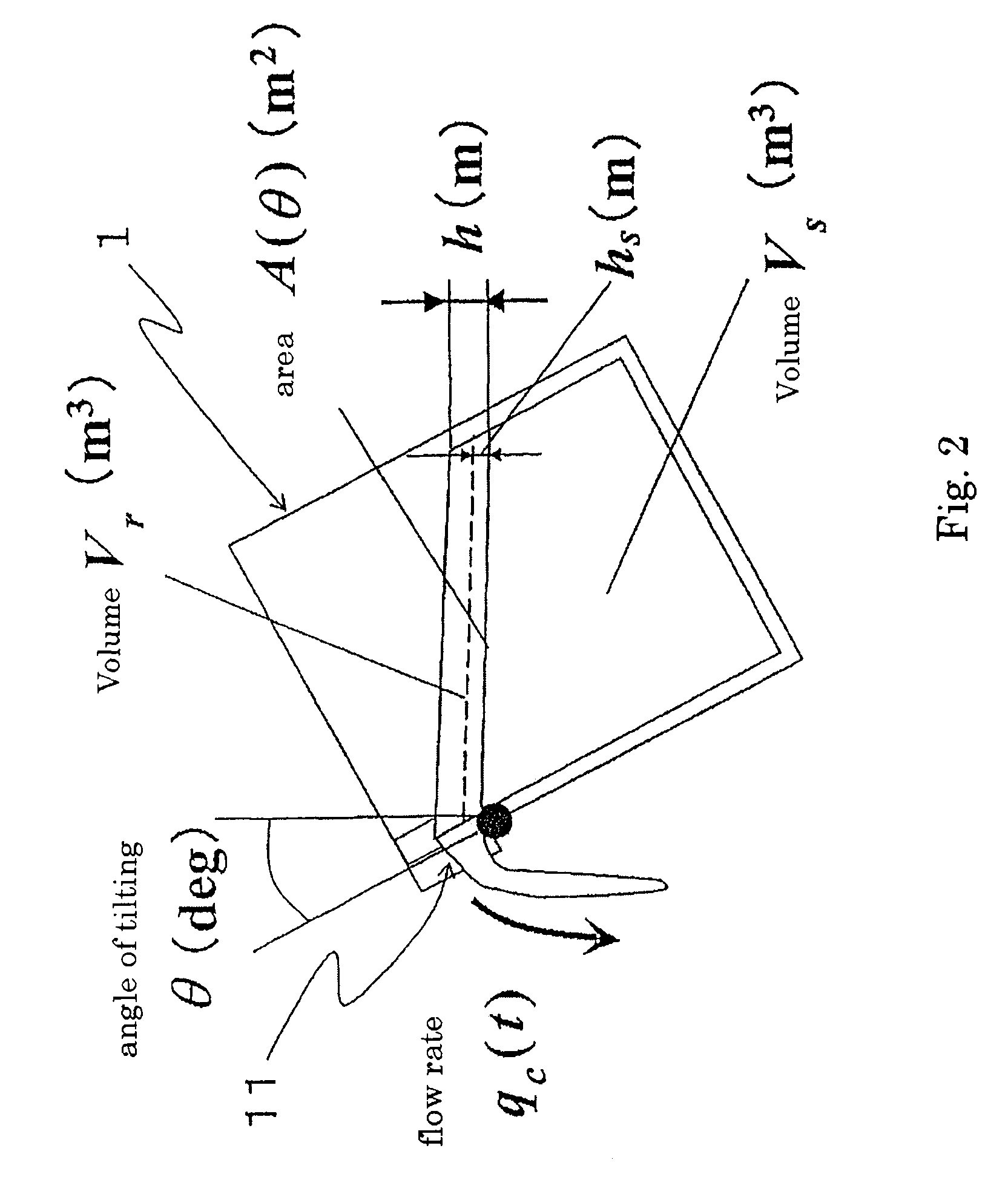
[0017]With the method of the present invention, the molten metal can be poured speedily and accurately into the mold to the level of the predetermined weight of the molten metal to be poured. This is because with this method the weight of the molten metal to be poured is estimated, and because if the estimated weight is the same as or above the predetermined weight, the backward tilting of the ladle is started.BEST MODE OF THE EMBODIMENT OF THE INVENTION
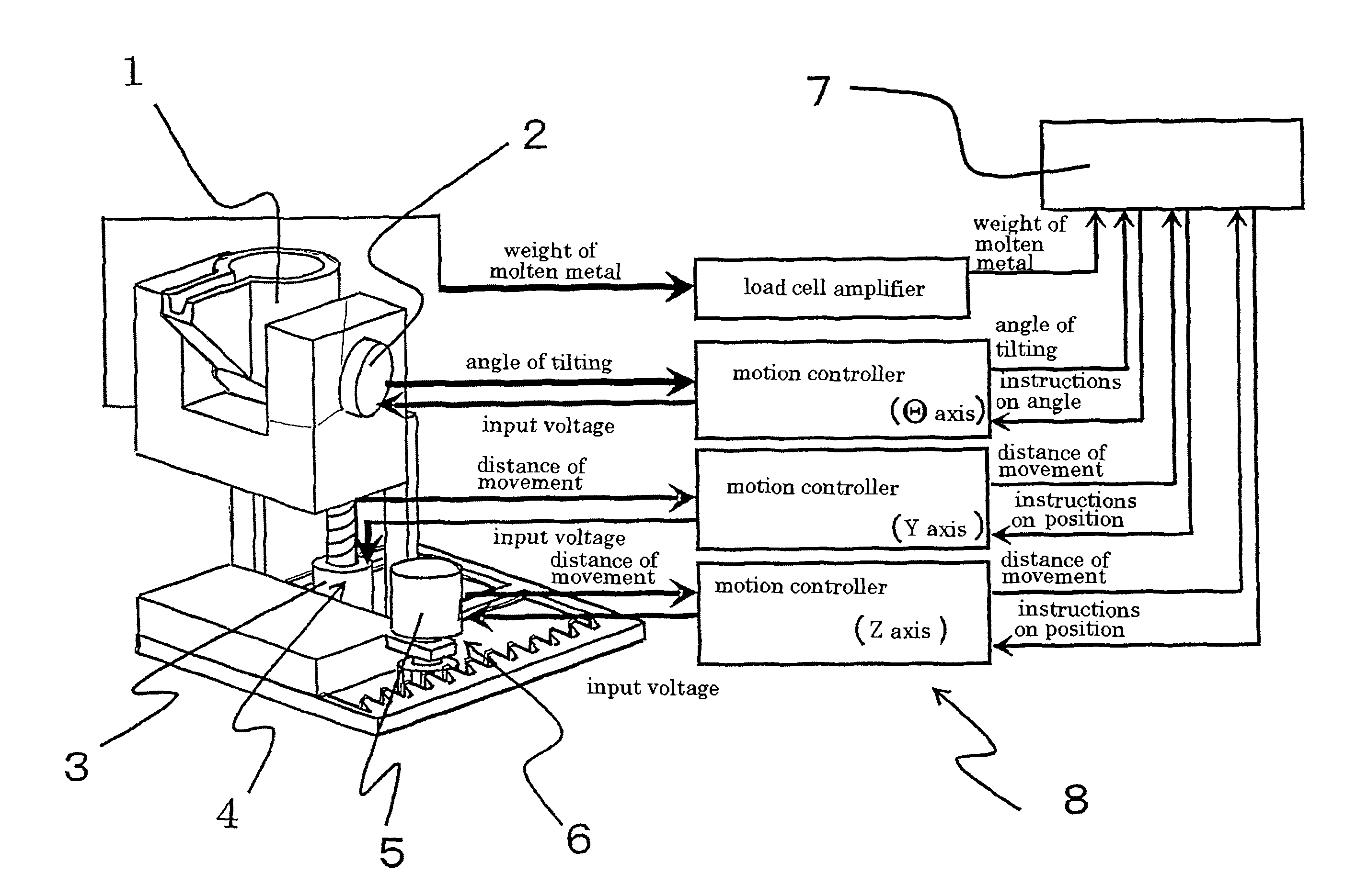
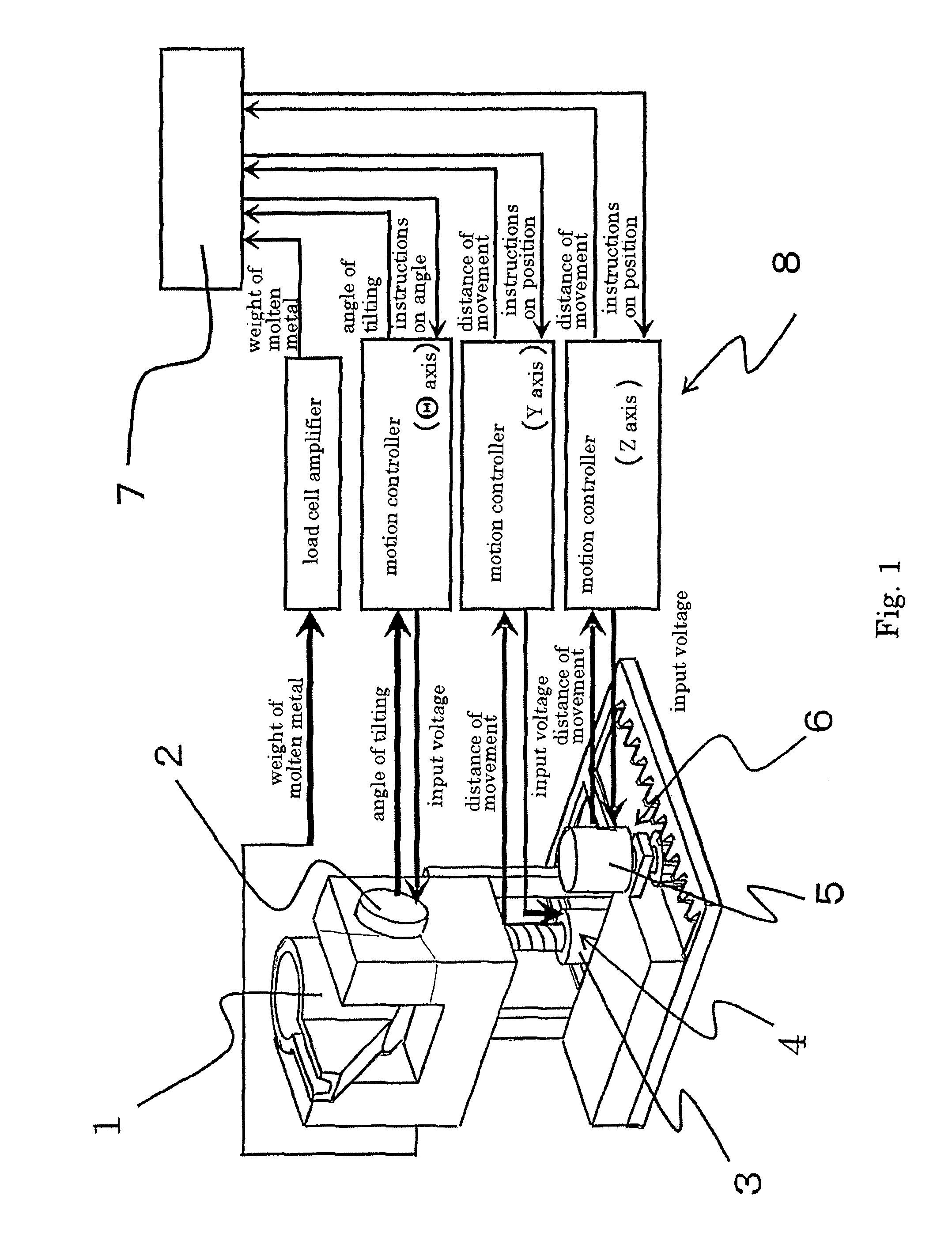
[0021]The ladle 1 has the output-axis of the servomotor 2 connected to its position of the center of gravity and is rotatably supported at its position. Around this position, the ladle can tilt forward toward the sprue of the mold and also can tilt backward, thereby distancing itself from the sprue of the mold (the movement to stop pouring). By having the ladle tilt around its center of gravity, the load that weighs on the servomotor is reduced.
[0022]Also, the transfer means 4, 6 move the ladle 1 backward and forward, and up and down in coordination with the tilting of the ladle 1, so as to have the molten metal accurately poured into the sprue of the mold, whereby the ladle can have an imaginary rotating axis at the tip of the outflow position as a fixed pouring point and rotate around it.

Problems solved by technology

Thus, to obtain accurately the desired weight of the molten metal that is poured into the mold is difficult.
However, the pouring method of Patent document 2 or non-Patent document 2 requires a number of basic experiments and the time to set up a necessary control system.
As a result, the time required for the backward tilting becomes longer.
Also, in the method of Patent document 2 or Non-Patent document 2, the fact that the response characteristics of a load cell that measures the weight of the molten metal that is poured greatly affects the accuracy of the weight is a problem.

Method used


Image

  • Tilting-type automatic pouring method and storage medium
  • Tilting-type automatic pouring method and storage medium
  • Tilting-type automatic pouring method and storage medium

Examples


Embodiment Construction

[0018]One embodiment of the tilting-type automatic pouring equipment to which the method of the present invention is applied is now explained based on the attached drawings. As shown in FIG. 1, the tilting-type automatic pouring equipment of the embodiment comprises a cylindrical ladle 1 having a outflow position that is rectangular; a servomotor 2 that tilts this ladle 1; a transfer means 4 that moves the ladle 1 vertically with a ball screw mechanism that converts the rotating movement of the output-axis of the servomotor 3 into linear movement; a transfer means 6 that moves the ladle 1 horizontally by means of a rack and pinion mechanism that converts the rotating movement of the output-axis of the servomotor 5 into linear movement; a load cell (not shown) that measures the weight of the molten metal in the ladle 1; and a control system 8 that utilizes a computer, which is a controller or a program logic controller (PLC 7) that calculates and controls the movements of the servomo...


PUM

PropertyMeasurementUnit
weightaaaaaaaaaa
weightaaaaaaaaaa
weightaaaaaaaaaa

Abstract

A tilting-type automatic pouring method for pouring molten metal from a ladle with an outflow position into a mold. The method includes tilting the ladle forward to pour molten metal into the mold, measuring a weight of poured molten metal, calculating a flow rate of the molten metal flowing out of the ladle based on the measured weight of poured molten metal, estimating a weight of molten metal that will be poured during a backward tilting. The method also includes estimating a total weight of molten metal based on the measured weight of poured molten metal and the estimated weight of molten metal that will be poured during the backward tilting and comparing the estimated total weight of molten metal to a predetermined weight. When the estimated total weight is equal to or larger than the predetermined weight, the backward tilting is started.

Description

TECHNOLOGICAL FIELD[0001]This invention relates to a tilting-type automatic pouring method and storage medium. More particularly, it relates to the tilting-type automatic pouring method that comprises holding a predetermined amount of molten liquid (molten metal) such as molten iron and aluminum in a ladle, then pouring it into a mold by tilting the ladle, and it also relates to the storage medium for programs for controlling the pouring of the molten liquid into the mold.BACKGROUND OF THE INVENTION[0002]Conventionally the tilting-type automatic pouring methods comprises one that controls the tilting speed of a ladle so that the constant flow rate of molten metal is maintained (see Patent document 1), that pours the predetermined weight of the molten metal in the shortest time (see Patent document 2), that controls the tilting speed of the ladle so that a desired flow pattern is realized (see Non-Patent document 1), or that uses a fuzzy control (see Non-Patent document 2).[0003]Pate...

Claims


Application Information

Patent Timeline
Patent Type & Authority Patents(United States)
IPC IPC(8): C21B13/00B22D37/00B22D39/04
CPCB22D41/06B22D46/00B22D37/00
Inventor NODA, YOSHIYUKITERASHIMA, KAZUHIKOMIYOSHI, TAKANORISUZUKI, MAKIOOTA, KAZUHIRO
Owner SINTOKOGIO LTD
Learn More