
Gun launched hybrid projectile

a hybrid and projectile technology, applied in the direction of vehicle position/course/altitude control, process and machine control, instruments, etc., can solve the problems of prohibitively expensive, lack of steering, and the inability to essentially steer the projectile in flight or re-launch once launched

Inactive Publication Date: 2012-02-14
UNITED STATES OF AMERICA THE AS REPRESENTED BY THE SEC OF THE ARMY
View PDF15 Cites 33 Cited by
  • Summary
  • Abstract
  • Description
  • Claims
  • Application Information

AI Technical Summary

Benefits of technology

[0005]It is another object of the present invention to provide a Hybrid Projectile for delivering an explosive payload to a target wherein the Hybrid Projectile may be steered in flight using relatively inexpensive means, and;

Problems solved by technology

However, such projectile essentially cannot be steered in flight or recalled once launched.
This lack of steering is with the possible exception of prohibitively expensive current proposed systems.
However, they require sophisticated programming, electronics, sensors, and seekers to define, select, then to hit a target; they therefore are extremely expensive.
These projectiles cannot be recalled and do not allow the user to select target based on visual information.
They are also much larger and heavier than existing projectiles of the same caliber.
By contrast an unmanned air vehicle (UAV) which can be tube or hand launched can be steered while in flight, however essentially a UAV cannot carry the desired heavy payloads of high explosives, moreover the UAV requires large motorized propellers which take space, consume large energy, may require batteries, and usually make noise which makes them easy to detect and track.
The UAV takes a long time to reach the target and can be blown off course by the wind, e.g., the hand or tube launched UAV does not have the appearance and shape of an existing projectile of the same caliber.

Method used


Image

  • Gun launched hybrid projectile
  • Gun launched hybrid projectile
  • Gun launched hybrid projectile

Examples


Embodiment Construction

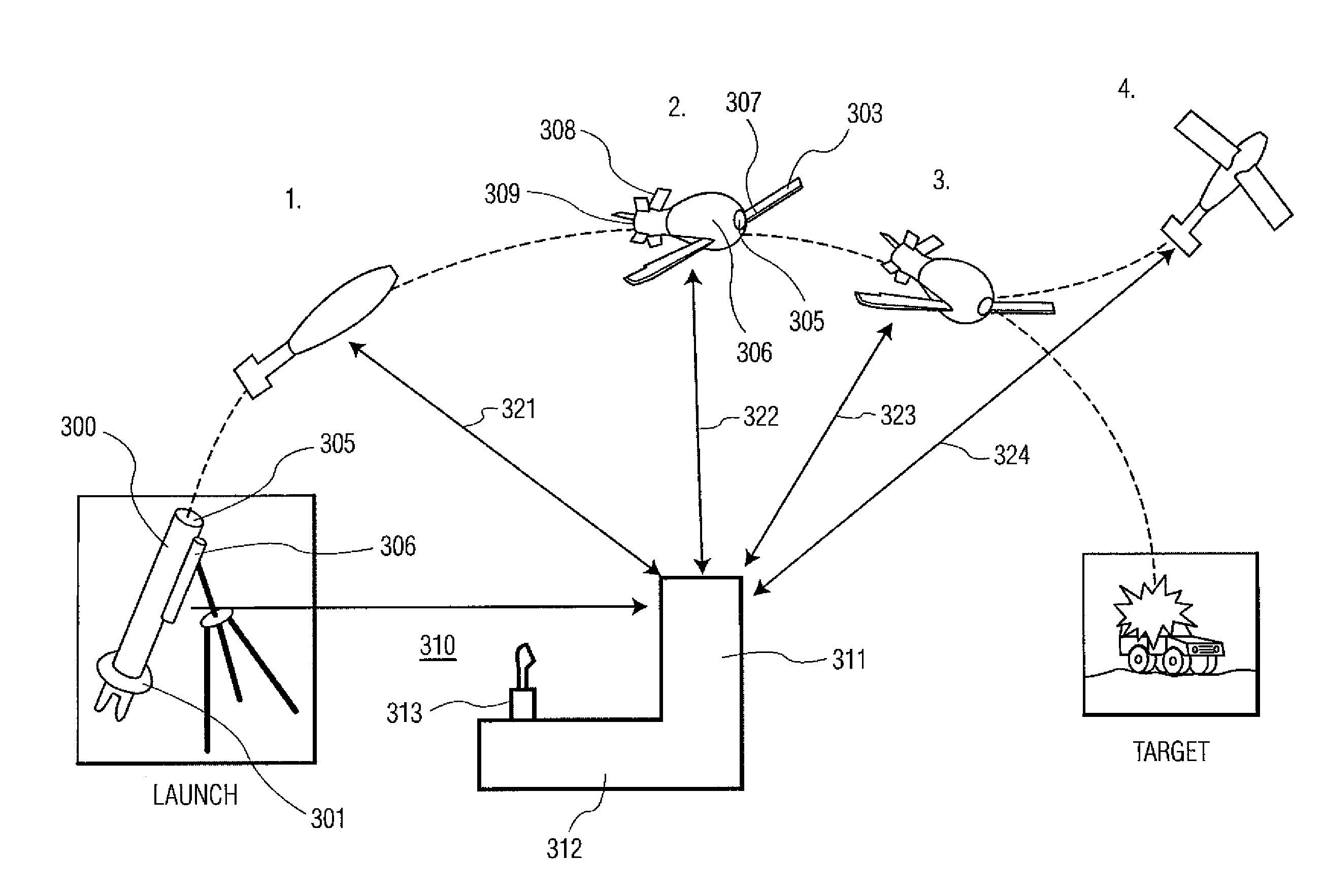
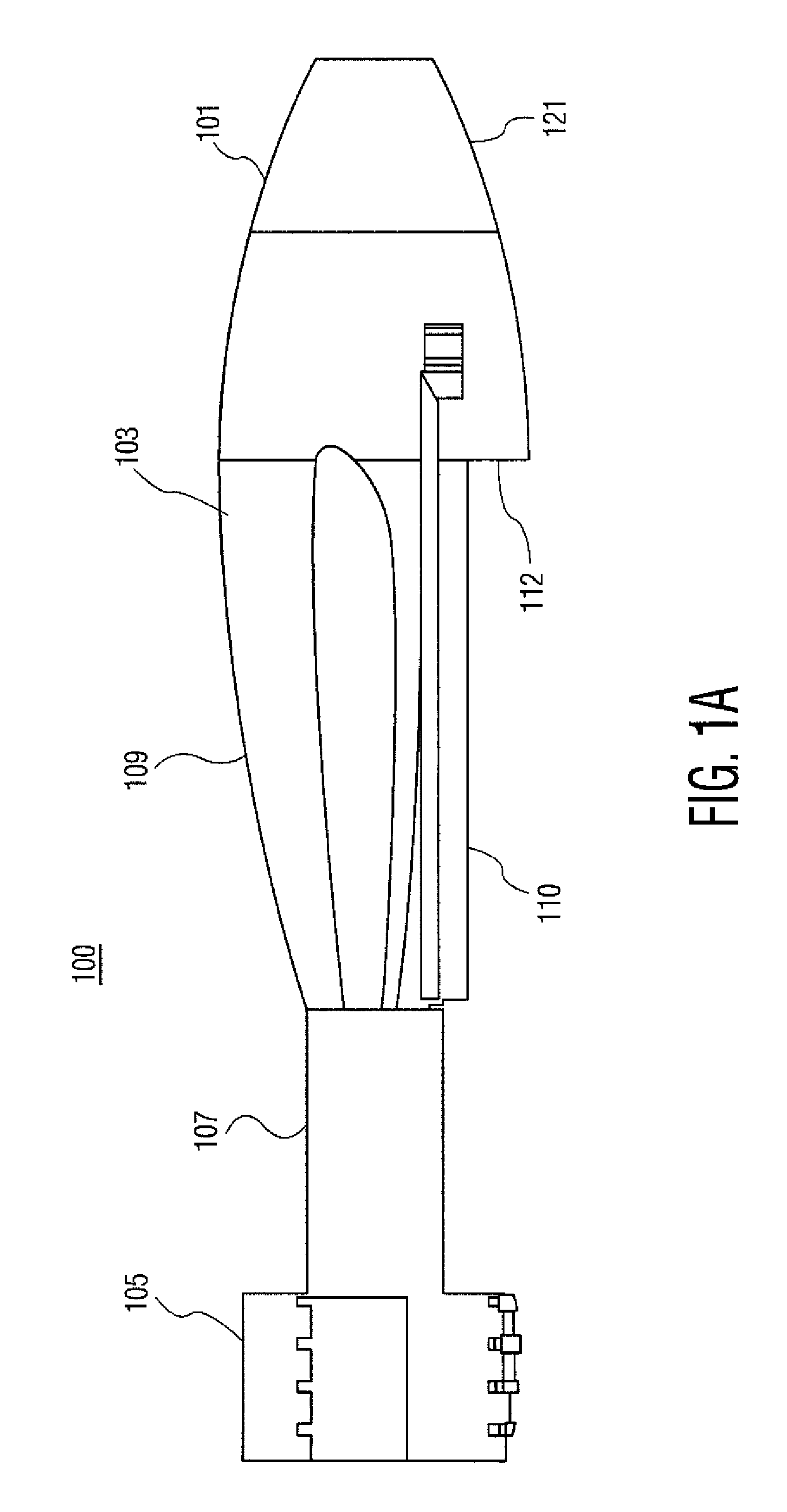
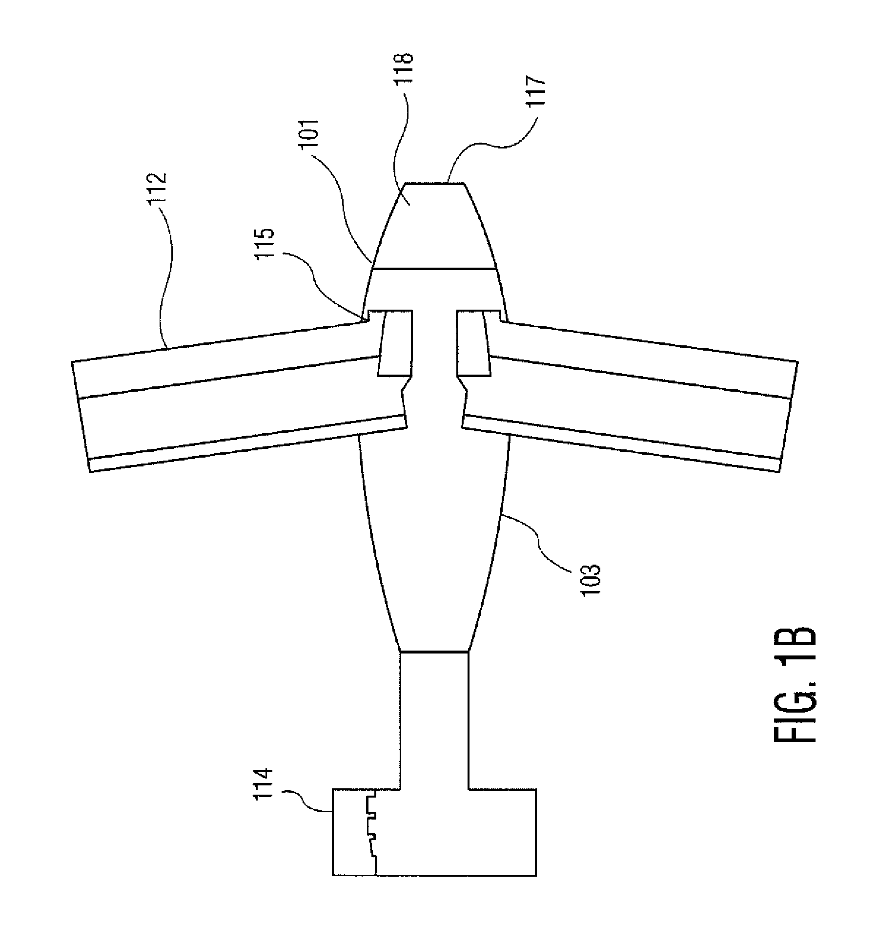
[0017]FIG. 3 illustrates the flight pattern of a projectile adapted according to this invention. A round 300 is routinely launched in cannon tube 301 purportedly aimed for the target depicted there at the right side of FIG. 3. In the fore end of the round there is an RE command link means 306 and a TV means 305, however such TV means could alternatively be positioned to the rear or on a side of the round; multiple TV means could also be employed. If desired, then at position 1 in flight, the TV, 305, and command link 306 can be activated by signal 321 from ground station 310. Then if desired, a signal 322 could be sent to the projectile, commanding it to transform. This is usually done after the projectile reaches apogee or top of the flight path (position 2). In response to such transform command, the projectile will “snap out” the (on board) wings 303 and fins 308. Ground station 310 has a work station 312 for an operator to utilize, a screen 311 for viewing the TV images, and a j...


PUM


Abstract

A Hybrid Projectile is provided for delivering an explosive payload to a target wherein the Hybrid Projectile may be steered in flight using relatively inexpensive means. The Hybrid Projectile is exteriorly configured in the same physical exterior configuration of conventional ammunition of various standard types so it can be launched in conventional manner from the same weapon systems. However, internal features allow the Hybrid Projectile to be transformed in flight from a command signal to deploy wings and fins, and in some projectiles to telescope open to deploy such wings and fins. An inexpensive televisual means is activated in the fore region of the round which through RF uplink command can be used to select a path, while motors on the wings can then be used to more precisely glide the projectile to a target, or otherwise to abort the target run.

Description

U.S. GOVERNMENT INTEREST[0001]The inventions described herein may be made, used, or licensed by or for the U.S. Government for U.S. Government purposes.BACKGROUND OF INVENTION[0002]Currently, projectiles are fired (gun launched) from military guns to defeat targets such as enemy soldiers, buildings and vehicles. These projectiles depend on either an energetic in the projectile, defeating the target with projectile shrapnel or blast overpressure, or by the kinetic energy of the projectile. Grenade, Shoulder Launched, Tank, Mortar, and Artillery projectiles may also be fired to defeat targets. A projectile can carry a heavy payload of high explosives, and is cannon launched with great force, so the projectile can travel up to long distances (such as 10 miles, e.g.) and deliver the destructive payload to the target. However, such projectile essentially cannot be steered in flight or recalled once launched. This lack of steering is with the possible exception of prohibitively expensive ...

Claims


Application Information

Patent Timeline
IPC IPC(8): F41G7/30B64C13/20F42B15/01F41G7/00F42B15/00
CPCF42B10/18F42B10/62F42B15/01F42B15/105F41G7/30G05D1/0038
Inventor MANOLE, LEON R.LOGSDON, JR., ERNEST L.PALATHINGAL, MOHAN J.SEBASTO, ANTHONY J.
Owner UNITED STATES OF AMERICA THE AS REPRESENTED BY THE SEC OF THE ARMY
Learn More