Induction device

a technology of induction device and core segment, which is applied in the direction of inductance, inductance with magnetic core, transformer/inductance details, etc., can solve the problems of reducing the and affecting the cooling effect so as to reduce the noise emitted by the induction device and achieve satisfactory cooling of the core segment surfa

Inactive Publication Date: 2012-02-14
ABB POWER GRIDS SWITZERLAND AG +1
View PDF8 Cites 2 Cited by
  • Summary
  • Abstract
  • Description
  • Claims
  • Application Information

AI Technical Summary

Benefits of technology

[0011]The present invention seeks to provide a way to reduce the noise emitted by the induction device with a satisfactory cooling of the core segments surfaces.
[0012]An object of the invention is achieved by providing an induction device. The device is characterised in that the spacers in at least one of the core gaps are arranged densely packed so as to form a compact filling in the gap, and that for at least some of the spacers the edges of the end faces of two neighboring spacers are arranged with chamfers allowing said neighboring spacers to form a common cooling duct for the cooling medium. The advantage with the arrangement is that, by arranging the spacers densely packed, an increased stiffness of the core leg will be achieved. An increased stiffness of the core leg will reduce the vibrations in the core leg and thus the emitted noise from the reactor will be reduced. At the same time the arrangement with the cooling ducts will achieve that the cooling of said core segments will be kept within a satisfactory level. The spacers are arranged with an upper end face, a lower end face and six side faces. By saying that the spacers are arranged densely packed, it is understood that the spacers are arranged so that the side faces of two neighboring spacers are arranged preferably in contact with, or at a very close distance from, each other.
[0013]According to one embodiment, the width of the chamfers is at least 20% of the radius of the spacer. Thereby a satisfactory cooling effect is achieved.
[0014]According to one further embodiment, the height of the cooling duct is at least 20% of the height of the spacer. Thereby a satisfactory cooling effect is achieved.

Problems solved by technology

A problem with this solution is that the cooling of the core segments will be reduced due to major loss of oil flow at the top and bottom core segment surfaces.
It is a well-known problem that the core gaps are a source of vibrations and noise in an electrical power reactor.
Such noise emitted from the reactor must be limited in order not to disturb surrounding areas, and the cost of eliminating said noise becomes prohibitive.
Cooling medium, such as oil, will transfer said vibrations from the core gap to the reactor tank, thus causing said noise to be emitted from said induction device.
The vibrations generated by the magnetic core together with the weight of the core and core assembly may force the rigid base structure beneath a reactor casing into vibration.
The casing sidewalls are rigidly connected to the base structure and may be driven into vibration by the stiff base members and propagate noise.

Method used


Image

  • Induction device
  • Induction device
  • Induction device

Examples


Embodiment Construction

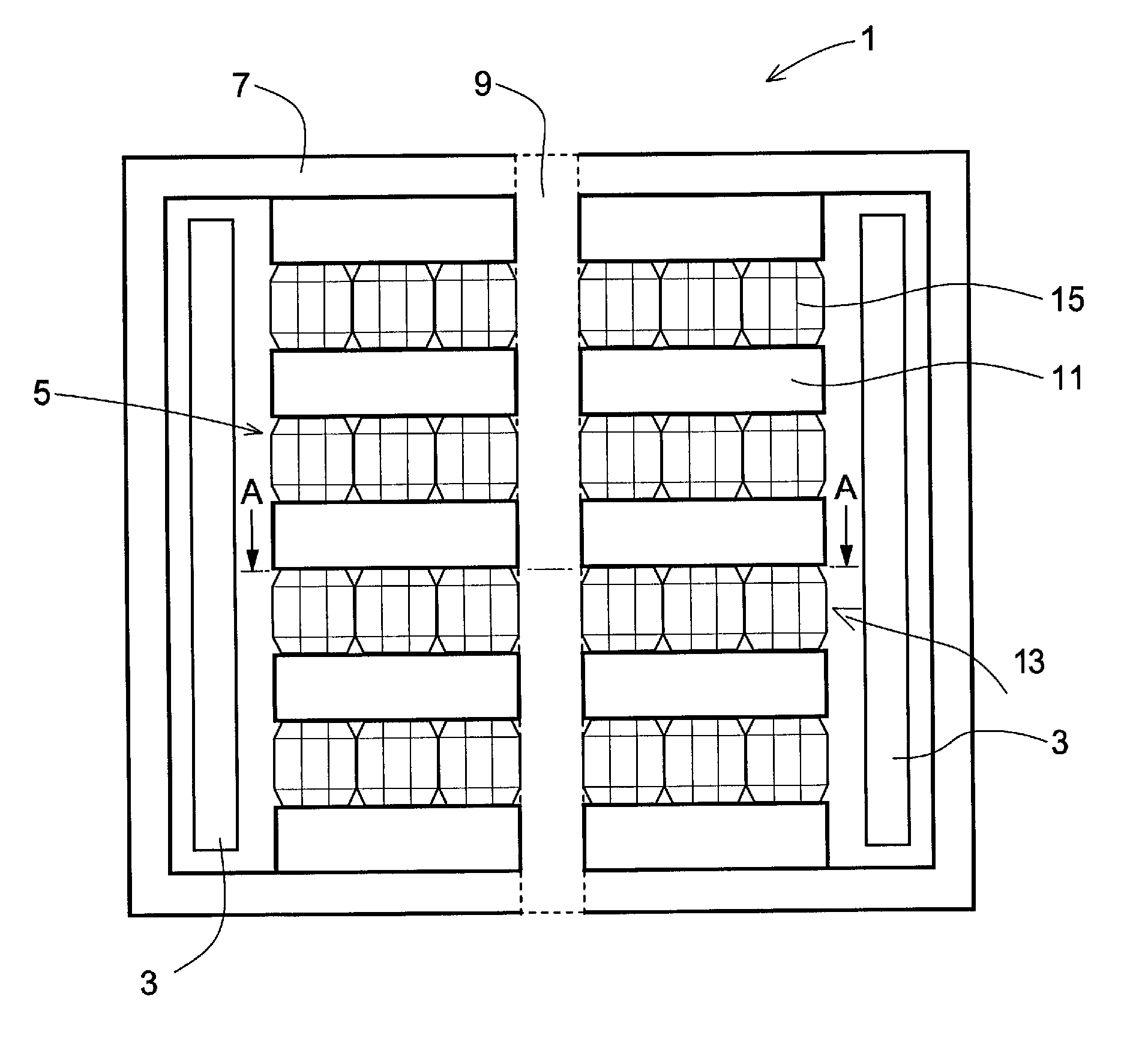
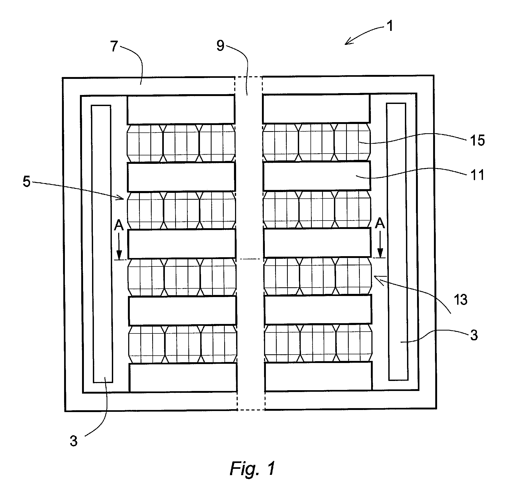
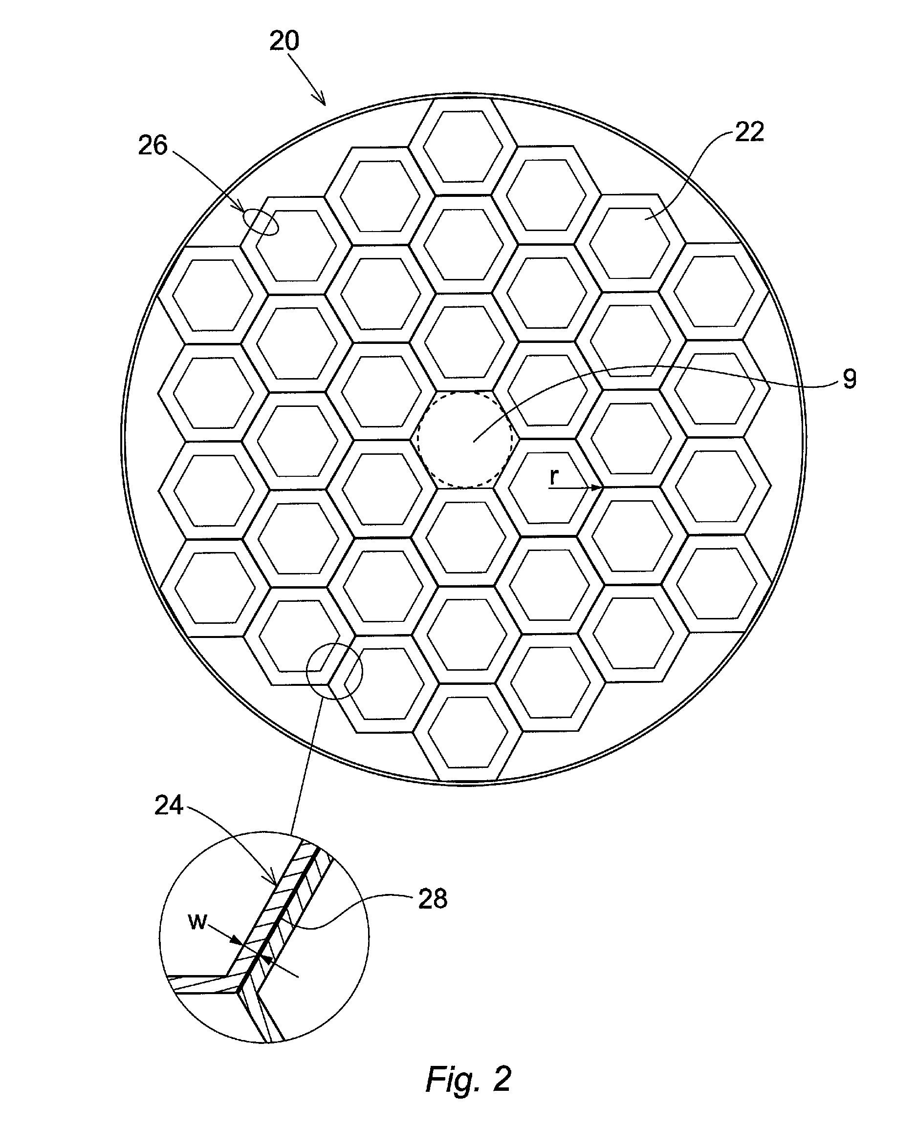
[0021]FIG. 1 illustrates an induction device 1 according to an embodiment of the invention. The induction device comprises one or more coils wrapped around a core forming at least one winding 3. The winding 3 is a well known accessory to this kind of device and is therefore only briefly mentioned in this context. The device further comprises a core frame 7 and one magnetic core leg 5 arranged between and interconnecting two yokes (not illustrated) in the core frame 7. The magnetic core leg 5, being cooled by a cooling medium such as oil, is comprised of a stack of core segments 11 of a magnetic material. The core leg 5 is arranged in compression in the core frame 7, and the core leg 5 is arranged with core gaps 13 arranged to separate the core segments 11. Further the core leg 5 is also arranged with a plurality of spacers 15, arranged in the core gaps 13 between the core segments 11. The spacers 15, typically made of a ceramic material such as steatite, have a cross-section of hexa...


PUM

PropertyMeasurementUnit
operating frequencyaaaaaaaaaa
voltageaaaaaaaaaa
widthaaaaaaaaaa

Abstract

An induction device for association with high voltage electric transmission systems having at least one core frame and at least one winding arranged around said core frame. The induction device has at least one magnetic core leg arranged in said core frame. The core frame includes a stack of core segments of a magnetic material being cooled by cooling medium, arranged in compression in the core frame, core gaps being arranged to separate the core segments, and a plurality of spacers, arranged in the core gaps between the core segments, with a cross section of hexagonal shape, having an upper and a lower end-face being in contact with the core segments. The spacers in at least one of the core gaps are arranged densely packed so as to form a compact filling in the core gap.

Description

CROSS-REFERENCE TO RELATED APPLICATIONS[0001]The present application is a continuation of pending International patent application PCT / EP2008 / 066051 filed on Nov. 24, 2008 which designates the United States and the content of which is incorporated herein by reference.FIELD OF THE INVENTION[0002]The present invention relates to an induction device, such as a shunt reactor to provide power of the order of several tens of MVA, to be used in association with high voltage electric transmission systems above 1 kV. The invention is particularly applicable to a shunt reactor for use in a power system, for example in order to compensate the capacitive reactance of long electricity power transport lines, which are generally high-voltage power lines or extended cable systems.BACKGROUND OF THE INVENTION[0003]The function of a shunt reactor is generally to provide a required inductive compensation necessary for power line voltage control and stability in high voltage transmission lines or cable ...

Claims


Application Information

Patent Timeline
Patent Type & Authority Patents(United States)
IPC IPC(8): H01F17/06
CPCH01F3/14H01F27/12H01F27/263H01F27/33H01F37/00H01F27/08H01F27/00
Inventor ERIKSSON, ANDERS BOFORSLIN, JULIA
Owner ABB POWER GRIDS SWITZERLAND AG
Why Eureka
Try Eureka