Windscreen wiper device, in particular for a motor vehicle

a technology for windshield wipers and motor vehicles, which is applied in the direction of vehicle cleaning, roofs, furniture parts, etc., can solve the problems of having to replace the entire windshield wiper device, the need for adequate construction space, and the impact of the wiper shaft, so as to achieve stable and secure mounting of the bearing, easy replacement, and good hold on the bearing

Inactive Publication Date: 2012-02-21
ROBERT BOSCH GMBH
View PDF18 Cites 32 Cited by
  • Summary
  • Abstract
  • Description
  • Claims
  • Application Information

AI Technical Summary

Benefits of technology

[0005]The windshield wiper device in accordance with the invention has the advantage that a retaining element is provided, which detachably connects the bearing to the support so that, in the case of an increased effect of force on the wiper shaft, only the bearing is separated from the support and must disappear within the vehicle body. In this case, the windshield wiper device itself always remains in its original position, wherein firstly, construction space is saved and secondly, the windshield wiper device will not be destroyed in a crash.
[0006]It is especially advantageous if the support has a receptacle to accommodate the bearing. The receptacle guarantees a secure hold of the bearing on the support.
[0007]If the bearing includes a tube, it is advantageously easy to fasten it on the support and reliably support the wiper shaft.

Problems solved by technology

In the case of a pedestrian impact with the body of the motor vehicle, the pedestrian can be injured by these projecting wiper shafts.
In this case, it is problematic first of all that adequate construction space has to be available to accommodate the windshield wiper device and, secondly, the entire windshield wiper device has to be replaced after a crash.
However, this is very costly and not practical for smaller vehicles.

Method used


Image

  • Windscreen wiper device, in particular for a motor vehicle
  • Windscreen wiper device, in particular for a motor vehicle
  • Windscreen wiper device, in particular for a motor vehicle

Examples


Embodiment Construction

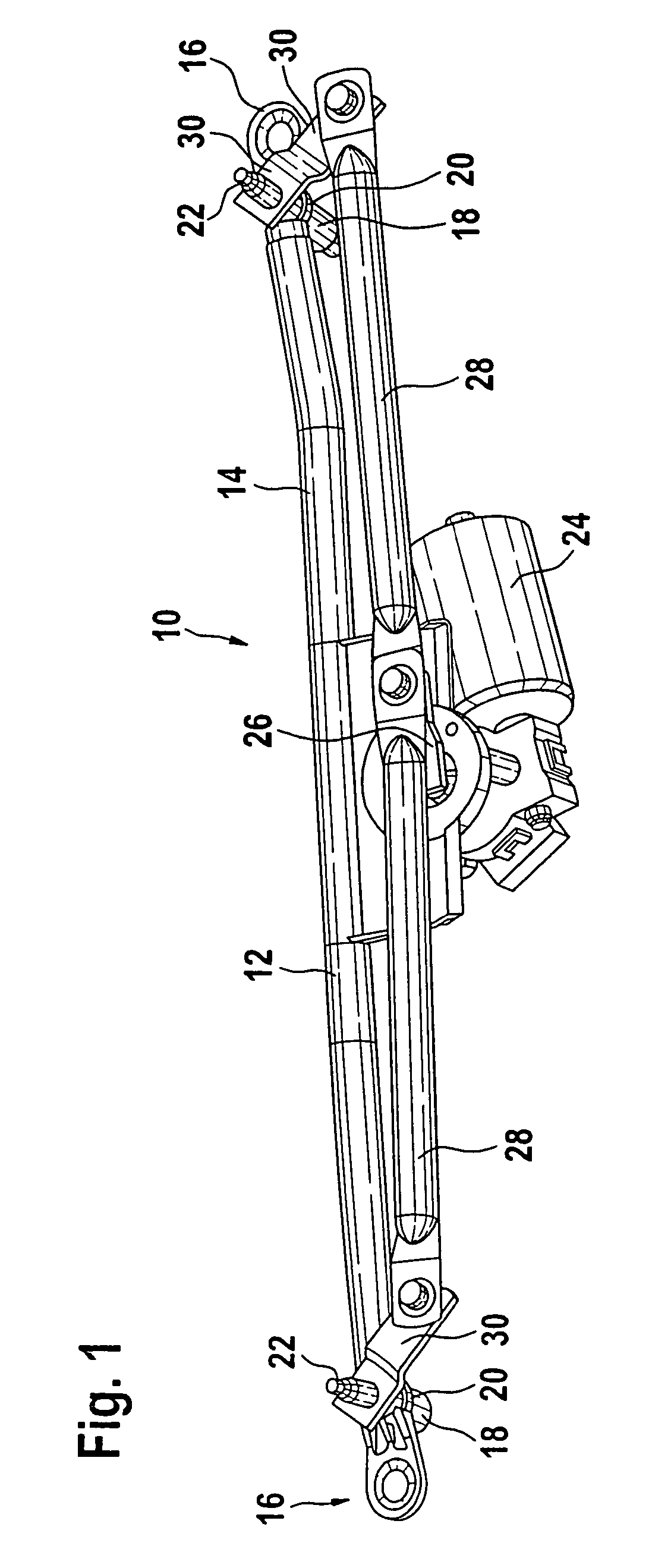
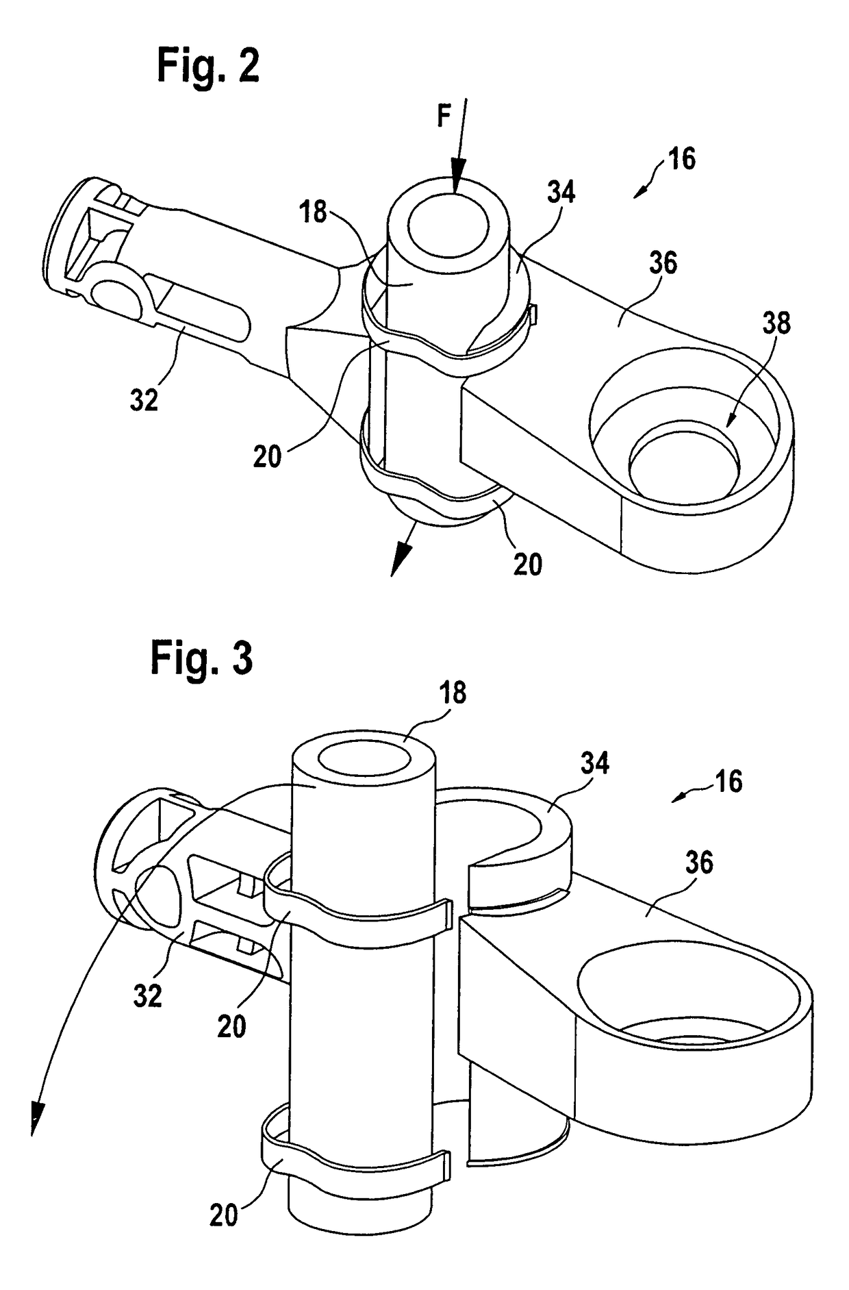
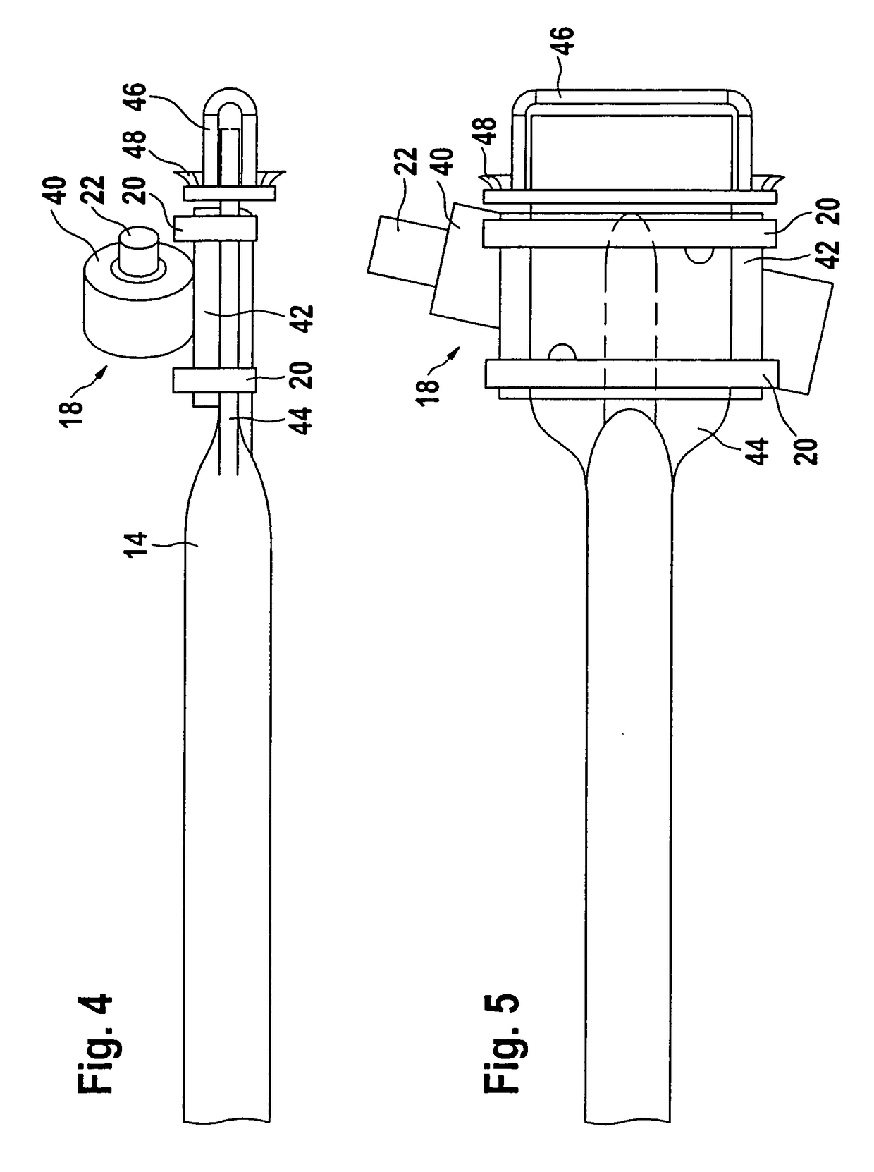
[0026]FIG. 1 depicts a perspective representation of a windshield wiper device 10 in accordance with the invention. It is comprised essentially of a support 12 made of a tube 14, and a bearing holder 16 is attached on each of its two ends. The bearing holders 16 of the support 12 each accommodate a bearing 18, which is fixed radially and axially by means of retaining elements 20 on the bearing holders 16 of the support 12. The bearing 18 support the wiper shafts 22, on which the wiper arms (not shown here) having wiper blades are fastened.

[0027]In addition, an electric motor 24 is attached as a drive device to the tube 14 of the support 12, and said electric motor is able to set the wiper shafts 22 into a pendulum motion via a crank mechanism. The windshield wiper device 10 is fastened to the body of the motor vehicle via the bearing holder 16 of the support 12. The drive device 24 drives a first crank 26, which is able to set the two thrust rods 28 into a back and forth motion. The...


PUM


Abstract

The invention relates to a windshield wiper device (10), in particular for a motor vehicle, comprising a support (12), on which a bearing (18) is arranged, which supports a wiper shaft (22). In this case, a retaining element (20) is provided, which detachably connects the bearing (18) to the support.

Description

BACKGROUND OF THE INVENTION[0001]The invention relates to a windshield wiper device, in particular for a motor vehicle.[0002]Numerous windshield wiper devices having a wiper shaft that is positioned in a bearing that is fastened on a support are already known, for example from DE-A 199 03 140. The wiper shafts are connected with wiper arms bearing the wiper blades and therefore project from the body of the motor vehicle. In the case of a pedestrian impact with the body of the motor vehicle, the pedestrian can be injured by these projecting wiper shafts. As a result, several methods have been developed to protect the pedestrian. Normally, the fastening of the windshield wiper device is provided with predetermined breaking points so that, in the case of an impact on the wiper shafts, the windshield wiper device can be torn from its fastening and descend into the interior of the body.[0003]In this case, it is problematic first of all that adequate construction space has to be available...

Claims


Application Information

Patent Timeline
Patent Type & Authority Patents(United States)
IPC IPC(8): B60S1/04B60S1/06
CPCB60S1/0425B60S1/0488Y10S248/90Y10S403/03B60S1/04
Inventor KRAUS, ACHIMSCHABANEL, FRANCOIS
Owner ROBERT BOSCH GMBH
Why Eureka
Try Eureka