Exhaust purification device of internal combustion engine

a technology of purification device and internal combustion engine, which is applied in the direction of machine/engine, exhaust treatment electric control, separation process, etc., can solve the problems of drop in the concentration abnormality of urea aqueous solution

Inactive Publication Date: 2012-02-21
TOYOTA JIDOSHA KK
View PDF27 Cites 11 Cited by
  • Summary
  • Abstract
  • Description
  • Claims
  • Application Information

AI Technical Summary

Benefits of technology

[0004]An object of the present invention is to provide an exhaust purification device of an internal combustion engine able to detect an abnormality in a urea aqueous solution inexpensively and reliably.
[0006]An abnormality of the urea aqueous solution, that is, a drop in concentration of the urea aqueous solution, for example, mainly occurs when a nonstandard urea aqueous solution is refilled or a liquid other than a urea aqueous solution is refilled. On the other hand, a drop in concentration of the urea aqueous solution is expressed as a drop in the NOx purification rate at the time of engine operation. Therefore, it is possible to detect an abnormality of the urea aqueous solution from a drop in the NOx purification rate at the time of engine operation right after the urea aqueous solution is refilled and therefore possible to detect an abnormality of the urea aqueous solution by an inexpensive method.

Problems solved by technology

An abnormality of the urea aqueous solution, that is, a drop in concentration of the urea aqueous solution, for example, mainly occurs when a nonstandard urea aqueous solution is refilled or a liquid other than a urea aqueous solution is refilled.

Method used


Image

  • Exhaust purification device of internal combustion engine
  • Exhaust purification device of internal combustion engine
  • Exhaust purification device of internal combustion engine

Examples


Embodiment Construction

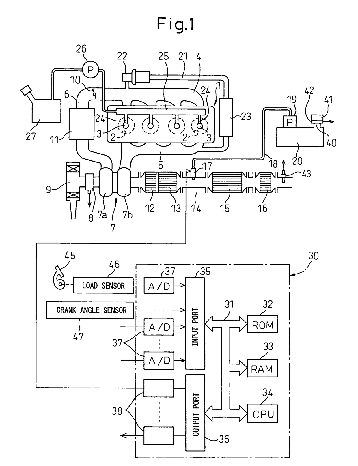
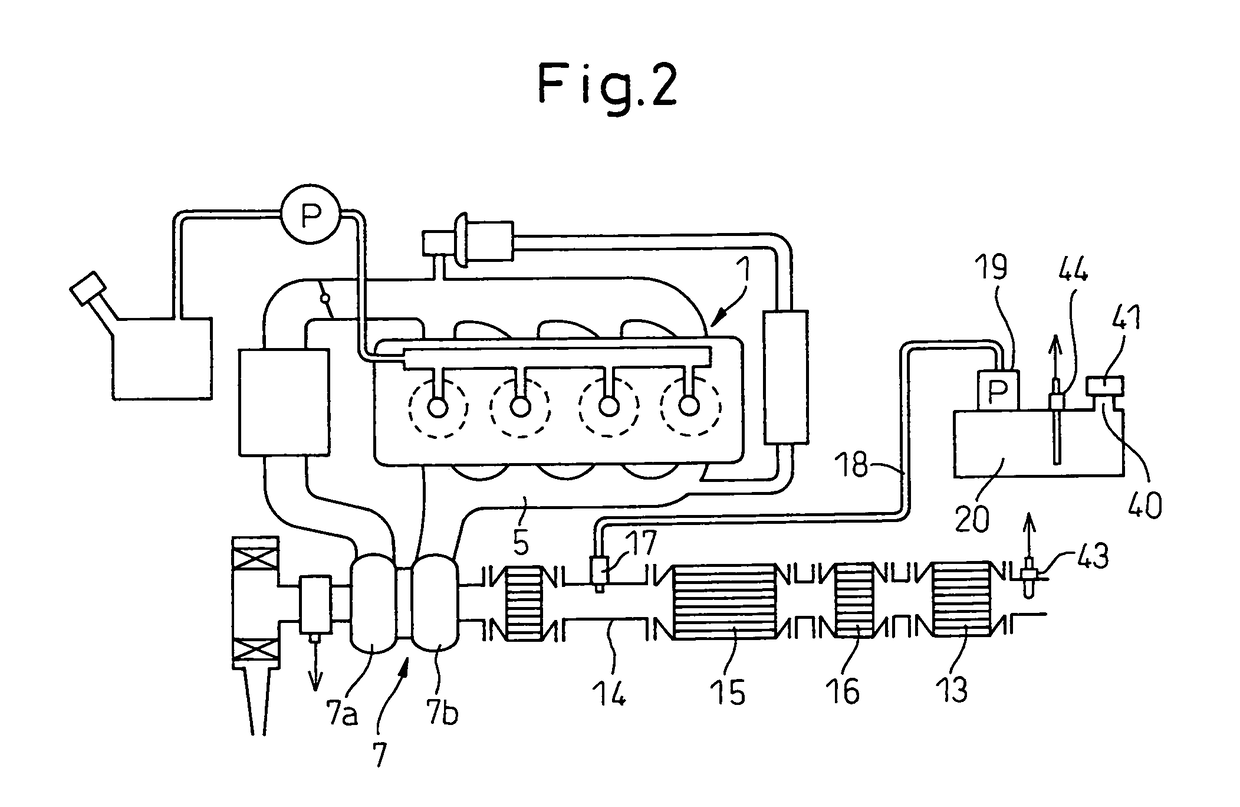
[0024]FIG. 1 shows an overview of a compression ignition type internal combustion engine.

[0025]Referring to FIG. 1, 1 indicates an engine body, 2 a combustion chamber of a cylinder, 3 an electronic control type fuel injector for injecting fuel into each combustion chamber 2, 4 an intake manifold, and 5 an exhaust manifold. The intake manifold 4 is connected through an intake duct 6 to the outlet of a compressor 7a of an exhaust turbocharger 7, while the inlet of the compressor 7a is connected through an intake air detector 8 to an air cleaner 9. Inside the intake duct 6, a throttle valve 10 driven by a step motor is arranged. Further, around the intake duct 6, a cooling device 11 for cooling the intake air flowing through the inside of the intake duct 6 is arranged. In the embodiment shown in FIG. 1, the engine cooling water is guided to the cooling device 11 where the engine cooling water cools the intake air.

[0026]On the other hand, the exhaust manifold 5 is connected to the inlet...


PUM

PropertyMeasurementUnit
liquid levelaaaaaaaaaa
liquidaaaaaaaaaa
angle of inclinationaaaaaaaaaa

Abstract

In an internal combustion engine, an NOx selective reduction catalyst is arranged in the engine exhaust passage and a urea aqueous solution stored in a urea aqueous solution tank is fed to the NOx selective reduction catalyst where the NOx is selectively reduced. Opening and closing of the urea aqueous solution refill port of the urea aqueous solution tank are detected and it is judged if the urea aqueous solution is refilled in the urea aqueous solution tank. When it is judged that the NOx purification rate has fallen to an allowable level or less at the time of engine operation right after the urea aqueous solution is refilled in the urea aqueous solution tank, it is judged that the refilled urea aqueous solution is abnormal.

Description

TECHNICAL FIELD[0001]The present invention relates to an exhaust purification device of an internal combustion engine.BACKGROUND ART[0002]Known in the art is an internal combustion engine arranging an NOx selective reduction catalyst in an engine exhaust passage, feeding an urea aqueous solution stored in an urea aqueous solution tank to the NOx selective reduction catalyst, and using the ammonia produced from the urea aqueous solution to selectively reduce the NOx contained in the exhaust gas, in which internal combustion engine a urea aqueous solution concentration sensor is arranged in the urea aqueous solution tank for detecting an abnormality of the urea aqueous solution (for example, see Japanese Patent Publication (A) No. 2005-83223).[0003]However, this urea aqueous solution concentration sensor is expensive. It is desirable to use another more inexpensive method.DISCLOSURE OF THE INVENTION[0004]An object of the present invention is to provide an exhaust purification device o...

Claims


Application Information

Patent Timeline
Patent Type & Authority Patents(United States)
IPC IPC(8): F01N3/00
CPCB01D53/9431B01D53/9495F01N3/2066B01D2257/404B01D2258/01F01N2610/02F01N2900/1806F01N2900/1814Y02T10/24B01D2251/2067F01N9/00F01N11/00F01N2610/1406F02B37/00F01N13/0097F01N13/009F01N2610/142Y10T137/7287Y02A50/20Y02T10/12Y02T10/40F01N3/18B01D53/94F01N3/04F01N3/28
Inventor TOSHIOKA, SHUNSUKEODA, TOMIHISAITOH, TAKEKAZUTANAI, YUTAKAWATANABE, SATOSHINAKAMURA, YOSHITAKA
Owner TOYOTA JIDOSHA KK
Why Eureka
Try Eureka