
Rotary parlour for milking of animals

a technology of parlour and animal, which is applied in the direction of milking devices, shafts and bearings, construction, etc., can solve the problems of wear surfaces having a longer working life, and achieve the effect of simple manner and longer working li

Active Publication Date: 2012-02-21
DELAVAL HLDG AB
View PDF14 Cites 3 Cited by
  • Summary
  • Abstract
  • Description
  • Claims
  • Application Information

AI Technical Summary

Benefits of technology

The present invention provides a circular rail member for a rotary parlour for milking animals that has a longer working life compared to conventional rail members. The wear surface of the rail member is designed to allow for angular movements between the parts of the rail member, reducing wear and tear. The connection between the parts of the rail member allows for easy replacement of the whole rail member without having to dismount and exchange the whole rail member. The connection is designed to allow for mutual adjustment movements between the parts of the rail member. The rail member has a separate second part comprising the wear surface that can be easily replaced. The bonding between the parts of the rail member can be a plate member or a suitable plastic material. The second part of the rail member can be an elongated wear strip or a protecting element. The first part of the rail member can be made up of two elongated rod elements or a beam element. The technical effects of the invention are improved durability and reliability of the rail member, reduced maintenance costs, and increased efficiency of the rotary parlour.

Problems solved by technology

Thus, the wear surfaces will have a longer working life.

Method used


Image

  • Rotary parlour for milking of animals
  • Rotary parlour for milking of animals
  • Rotary parlour for milking of animals

Examples


Embodiment Construction

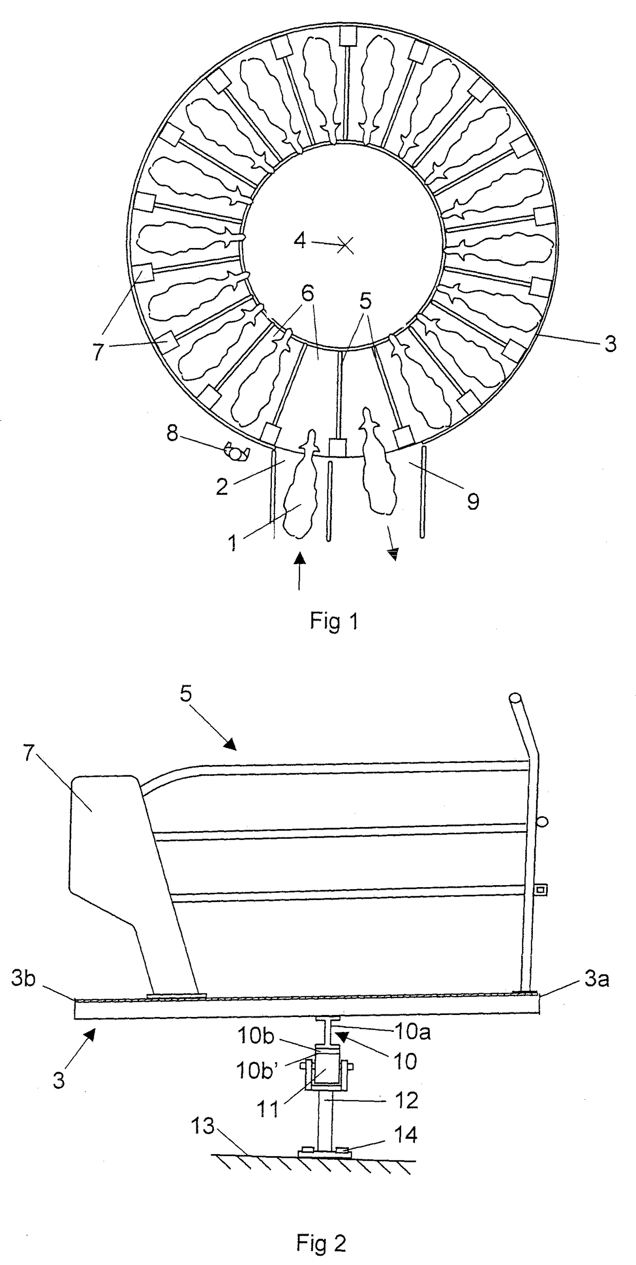
[0020]FIG. 1 shows a rotary parlour for milking of cows 1. The cows 1 to be milked walks through an entry 2 to enter an annular platform 3. The platform 3 is rotatably arranged around a substantially vertical axis 4. A plurality of fence arrangements 5 are mounted on the platform, which divide the platform 3 into stalls 6 for receiving individual cows 1. In this case, the fence arrangements 5 have a substantially radial extension on the platform 3 in relation to the vertical axis 4. Cabinets 7 are arranged at an outer radial position of the platform 3. In this case, the cabinets 7 constitute a supporting element of the fence arrangements 5. Each cabinet 7 has an inner space, which may accommodate milking equipment and other components in the stall 6. In this case, the stalls 6 are arranged such that the cows face inwards from the stalls 6 and operators 8 work from the outside of the annular platform 3. An operator 8 may, for example, attach milking members to the cows 1 when they ha...


PUM


Abstract

The invention relates to a rotary platform for milking of animal. The rotary parlor comprises a platform (3), a circular rail member (10) connected to a lower surface of the platform (3) and a plurality of rolling members (11) having a wear surface (11′) adapted to be in contact with a wear surface (10b″) of the rail member (10). The rail member (10) comprises a first part (10a, 17, 18a, b) connected to the platform (3), a second part (10b, 18c) comprising said wear surface (10b″) and a connection arranged between said first part (10a, 17, 18a, b) of the rail member and said second part (10b, 18c) of the rail member, which connection is adapted to allow angular movements between the first part (10a, 17, 18a, b) and the second part (10b, 18c) of the rail member (10).

Description

THE BACKGROUND OF THE INVENTION AND PRIOR ART[0001]The present invention relates to a rotary parlour for milking of animals, wherein the rotary parlour comprises an platform having a surface to support animals to be milked, a circular rail member connected to a lower surface of the platform and a plurality of rolling members having a wear surface adapted to be in contact with a wear surface of the rail member such that the platform is rotatably arranged on the rolling members.[0002]A conventional rotary parlour comprises a circular rail member provided with a substantially plane wear surface to be in contact with corresponding plane wear surfaces of rolling members arranged on the underside of the platform. During operation of the rotary parlour, parts of the platform will be deflected by the weight of the cows. The deflection of the platform occurs especially when the cows walk on and leave the platform. Such deflections of the platform may result in locally turning motions of the ...

Claims


Application Information

Patent Timeline
Patent Type & Authority Patents(United States)
IPC IPC(8): A01K1/12A01J5/00
CPCA01K1/126E04B1/346F16C13/00
Inventor OLIVER, CHRISTOPHER K
Owner DELAVAL HLDG AB
Learn More