Orthopedic plate for use in fibula repair

a technology for orthopedic plates and fibulas, applied in the field of orthopedic plates, can solve the problems of weakened plates, distorted screws, and more variability, and achieve the effects of reducing the risk of fracture, and improving the quality of li

Active Publication Date: 2012-02-21
WRIGHT MEDICAL TECH
View PDF58 Cites 62 Cited by
  • Summary
  • Abstract
  • Description
  • Claims
  • Application Information

AI Technical Summary

Benefits of technology

[0009]The plate has an elongate central trunk portion including one or more screw holes separated from each other by a waist shaped linking portion along a longitudinal axis. The plate further has a set of arms including screw holes which are placed at an equal distance from the longitudinal axis but which diverge asymmetrically from the longitudinal axis to avoid conflicts in the screw placement of the paired arm, specifically, so that the screws of a set of arms avoid impinging on each other. The plate is radiused about the inferior surface, (i.e. the surface which faces toward and which may, but does not have to fully contact the bone), with a curvature corresponding generally to the curvature of a bony surface. The pair of arms continue this curvature and the through holes are placed so that the angle of the longitudinal axis of the screws converge in the direction of the distil end of the screw. The screw holes are placed with the longitudinal axis perpendicular to a tangent to the top surface of the arm with the effect that the longitudinal axes of the screws converge in the direction of the distil end. The convergence of the screw holes increases the pull-out strength of the screws.
[0011]While the screws are at convergent angles, the screws typically do not in fact impinge on each other, or conflict in their placement since each of the arms of the plate in a pair form a different angle to the central trunk so that the longitudinal axis of the screws are offset from each other along the length of the plate. The radiused configuration of the plate is designed to increase operating room efficiency by facilitating commonly desirable shapes while maintaining the required strength and by permitting bending without deforming the screw holes. This results in making customization in anticipation or during surgery easier.
[0012]The screws useful with the plate of the present invention are self-starting, self-tapping screws including the option of partial or full cannulation. The screws include a unique cutting end having multiple flutes, and preferably 2 or 3 flutes about a conical recess. The screws further include a partial taper of the inner diameter in the proximal end over the first several thread turns, for example over 2-8, and preferably over 3-5 turns in order to increase the fatigue life of the screw as well as providing potential physiological advantages in use. The screws further include a torque driving recess that may be a hexagon, a torx shape, or a modification of a torx shape, i.e. a multilobe shape having from 3 to 12 lobes, and preferably having 4 to 8 rounded recesses or lobes. The recess can be of a constant size in the direction of the longitudinal axis, or can taper inward along the longitudinal axis of the screw toward the bottom of the recess. The screws have a low profile, head which is rounded at the junction of the head and the shaft, and also rounded from the maximum diameter toward the top surface or the proximal end relative to the insertion tip, which includes the torque driving recess. This rounded low profile head keeps the screw from having any sharp projecting edges which could provide an irritation to the tissue in the vicinity of the plate and further seats in the plate so that no more than 10% by volume of the screw head projects from the plate.
[0013]The instruments for use with the system are well-balanced and ergonomically designed with sufficiently long handles to place the surgeon's hands outside of the line of radiation and designed to reduce fatigue in the operating room.

Problems solved by technology

While there is a wide variety in the exact shape and mass of all bones, these variations become more problematic in providing orthopedic implants for small bone applications since there is less room on and about the bone for the surgeon to place and fix the construct.
These bones are finer and have less surface area for placement of an implant, and less mass for the placement of screws and as a result, individual variations become more problematic for orthopedic plates of stock design.
Consequently, surgeons have tended to rely on the use of screws and wires for reconstruction or have had to resort to operating room contouring procedures which can weaken the plates and / or distort the screw holes within the plates.
This is a particular problem in instances in which either variable locking mechanisms are used, or in which locking screws are used with the plates.
One problem that needs to be avoided in the delicate environment of the small bone area is the interference of screws, with other screws, and with the function of ligaments and tendons.
While it may be desirable to design an orthopedic plate so that securing screws converge in order to cause compression or increase the pullout strength, it is difficult when a screw impinges on or conflicts with the desired placement of another screw.
These factors are complicated by the relative lack of soft tissue and the presence of ligaments and tendons in the small bone areas.
These fractures typically occur when the foot is subjected to axial loading and is in supination, such as can happen during a skiing accident.
The talus rotates externally and the fibula fails which results in an oblique fracture beginning at the ankle joint and extending proximally from anterior to posterior.

Method used


Image

  • Orthopedic plate for use in fibula repair
  • Orthopedic plate for use in fibula repair
  • Orthopedic plate for use in fibula repair

Examples


Embodiment Construction

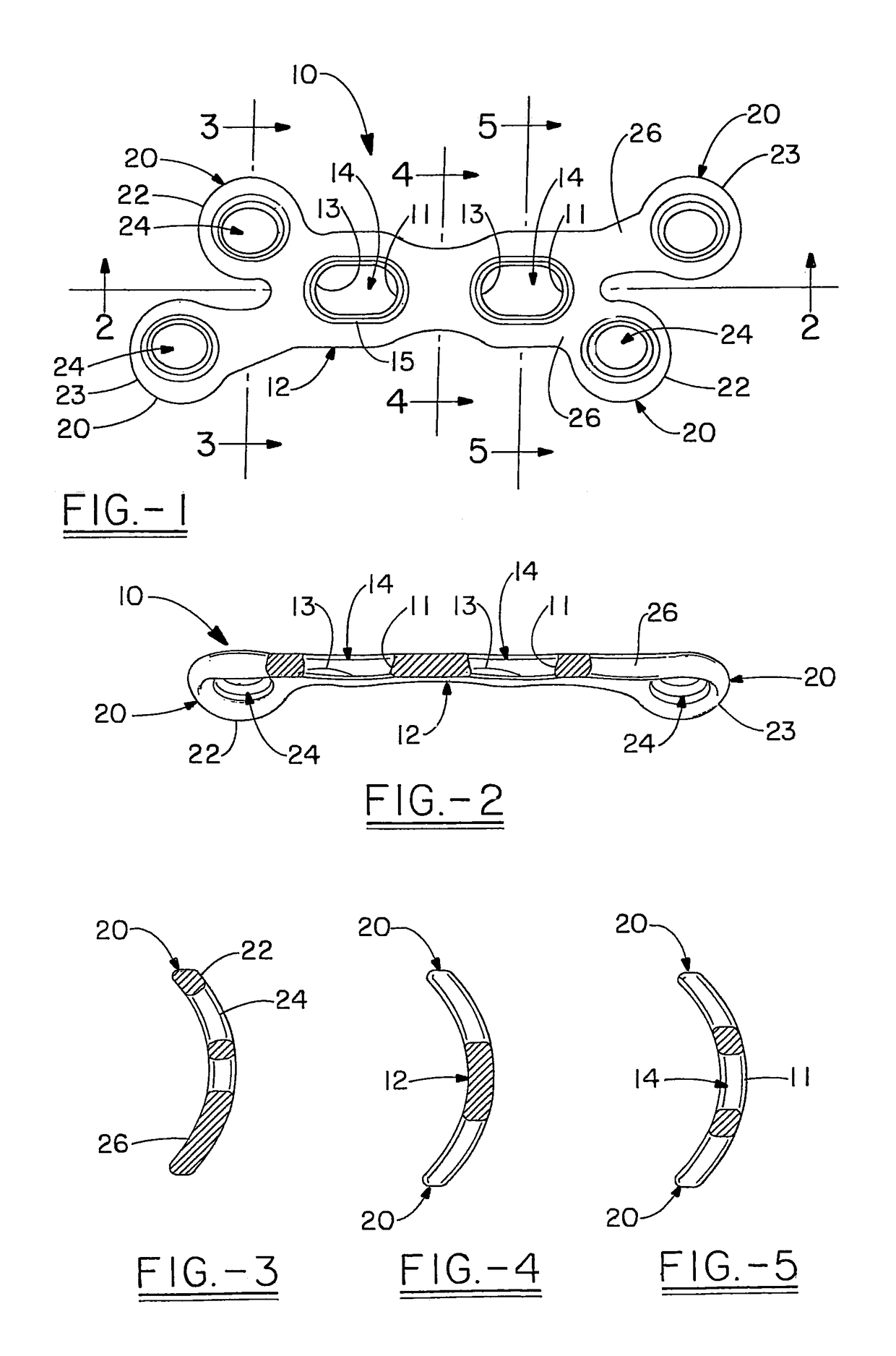
[0033]The plate 10 of the present invention is shown having a bilaterally asymmetric shape with either one or two pairs of legs extending from a central trunk portion 12 defining the longitudinal axis of the plate. As shown the trunk portion 12 includes two screw holes or slots 14 along the longitudinal axis. However, as can be seen from FIGS. 12 through 18 the plate can be presented in a version which has a plurality of screw holes, for example up to 8 or more. The number of screw holes in the trunk portion 12 will depend on the length of the plate, and may range from 0 to 8, and more preferably from 2 to 4. In one embodiment these holes are compression holes or translation slots. The compression holes 14 are preferably slotted or elongated and optionally may have a larger radius area 11 on each of the screw holes facing in the same direction, and a smaller radius area 13 in order to induce a compression toward the smaller radius end. The holes may also or alternatively have a shal...


PUM


Abstract

The present invention relates to an orthopedic plate for use in repair of a fibula. The plate has a Y-shaped profile which has the contour of a spoon where the bowl includes a terminal pair of arms that form differing angles and lengths relative to the trunk portion of the plate. The arms include locking screw holes where the screws converge toward each other, but do not impinge so as to provide-multiplanar fixation.

Description

CROSS-REFERENCE[0001]This application is a Continuation-in-Part application based on U.S. patent application Ser. No. 11 / 340,028 filed on Jan. 26, 2006 and on U.S. Provisional Application Ser. No. 60 / 648,364 filed on Jan. 28, 2005.FIELD OF THE INVENTION[0002]The present invention relates to an orthopedic plate in particular for surgical repair or reconstruction of a fibula and to a method for its use.BACKGROUND OF THE INVENTION[0003]The field of orthopedic medicine has grown tremendously in the past fifty years as surgical techniques, implants and instrumentation have developed and been improved. The small bones are frequently subject to the need for re-constructive surgery for example, as a result of trauma, to counteract the effects of aging or to repair congenital deformities and trauma and spinal areas. While there is a wide variety in the exact shape and mass of all bones, these variations become more problematic in providing orthopedic implants for small bone applications sinc...

Claims


Application Information

Patent Timeline
Patent Type & Authority Patents(United States)
IPC IPC(8): A61B17/80
CPCA61B17/8061
Inventor DUCHARME, DUSTINDEN HARTOG, BRYAN D.LEWIS, DEREK S.
Owner WRIGHT MEDICAL TECH
Why Eureka
Try Eureka