
Power converter with improved line transient response, control circuit for power converter, and method for improving line transient response

a technology of power converter and control circuit, which is applied in the direction of power conversion systems, dc-dc conversion, instruments, etc., can solve the problems of insufficient response of the entire circuitry, inapplicability of prior art methods to circuit structures, and the solution proposed by prior art to feed forward the reference voltage vref, etc., to achieve the effect of improving the line transient respons

Inactive Publication Date: 2012-02-21
RICHTEK TECH
View PDF3 Cites 1 Cited by
  • Summary
  • Abstract
  • Description
  • Claims
  • Application Information

AI Technical Summary

Benefits of technology

The present invention provides a power converter with improved line transient response. This is achieved by a power stage circuit including at least one power transistor switch which operates to convert an input voltage to an output voltage, an error amplifier comparing a feedback signal with a reference signal to generate an error signal, an input voltage instant variation extraction circuit extracting an instant variation of the input voltage and generating a signal relating to the instant variation, and a PWM comparator generating a PWM signal according to at least a ramp signal, the error signal, and the signal relating to the instant variation. The power converter also includes an output voltage feedback circuit generating a second feedback signal relating to the output voltage. The technical effects of this invention include improved stability, reduced ripple, and improved control accuracy.

Problems solved by technology

The above mentioned prior art has the following drawback: when a line transient occurs in the input voltage, for example because of an unstable power supply or other reasons, the response of the entire circuitry is not quick enough.
This prior art method is not applicable to the circuit structure wherein the reference voltage Vref is a constant.
Furthermore, the solution proposed by this prior art to feed forward the reference voltage Vref can only be applied to buck converter, but can not be applied to boost converter, inverter converter, and other power converters.

Method used


Image

  • Power converter with improved line transient response, control circuit for power converter, and method for improving line transient response
  • Power converter with improved line transient response, control circuit for power converter, and method for improving line transient response
  • Power converter with improved line transient response, control circuit for power converter, and method for improving line transient response

Examples


Embodiment Construction

[0026]Please refer to FIG. 8, which shows the first embodiment of the preset invention. The present invention obtains an instant variation ΔV of an input voltage IN and converts it by a proper ratio (K, where K can be any positive or negative real number and its absolute value can be more than, equal to, or less than 1) by an input voltage instant variation extraction circuit (ΔV·K) 21. Subsequently, the result (ΔV·K) is directly added to an output of the error amplifier EA 22 to speed up the response to the input voltage line transient.

[0027]More specifically, as shown in FIG. 8, the power converter with improved line transient response of the present invention comprises an error amplifier (EA) 12, a PWM comparator 14, a driver circuit 16, an input voltage instant variation extraction circuit 21, and a power stage circuit 28, wherein the circuits other than the power stage circuit 28 form a control circuit 20. The power stage circuit 28 converts an input voltage IN to an output vol...


PUM


Abstract

The present invention discloses a power converter with improved line transient, comprising: a power stage circuit including at least one power transistor switch which operates to convert an input voltage to an output voltage; an error amplifier comparing a feedback signal with a reference signal to generate an error signal; an input voltage instant variation extraction circuit extracting an instant variation of the input voltage and generating a signal relating to the instant variation; and a PWM comparator generating a PWM signal according to at least a ramp signal, the error signal, and the signal relating to the instant variation, to thereby control the operation of the power transistor switch in the power stage circuit.

Description

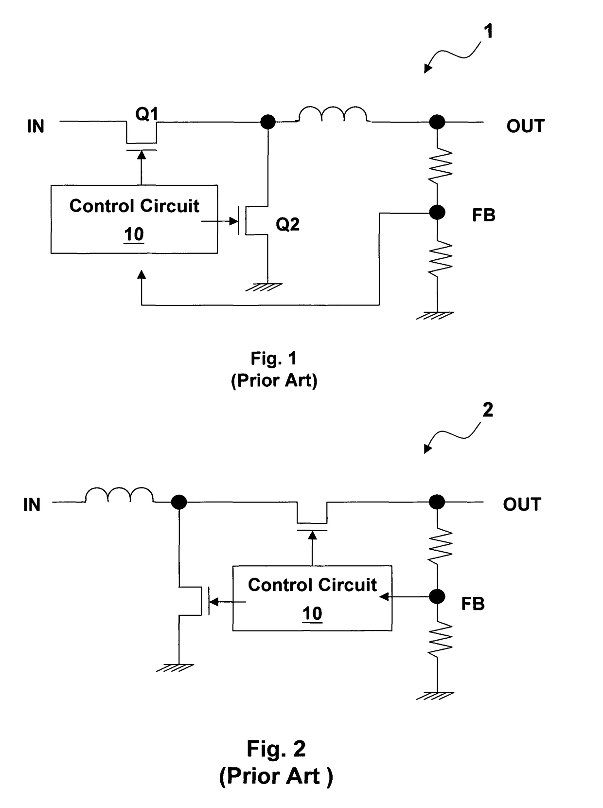
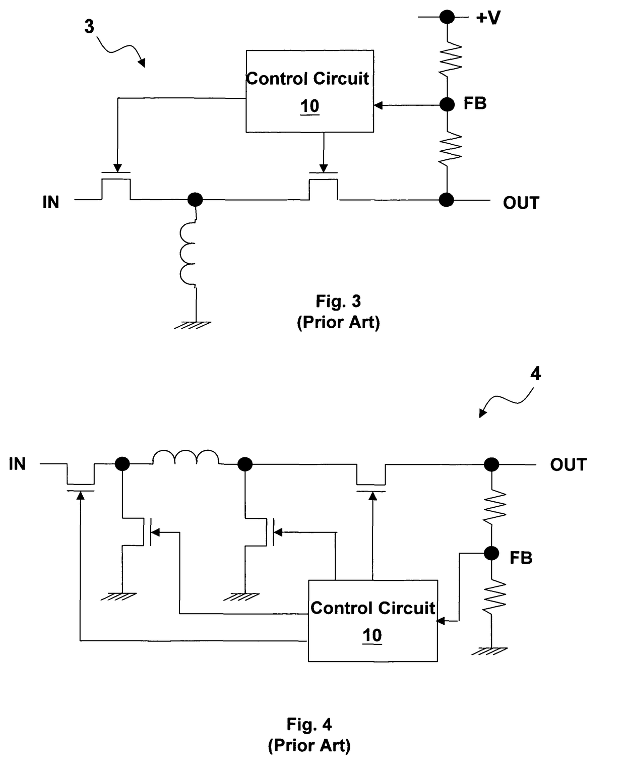
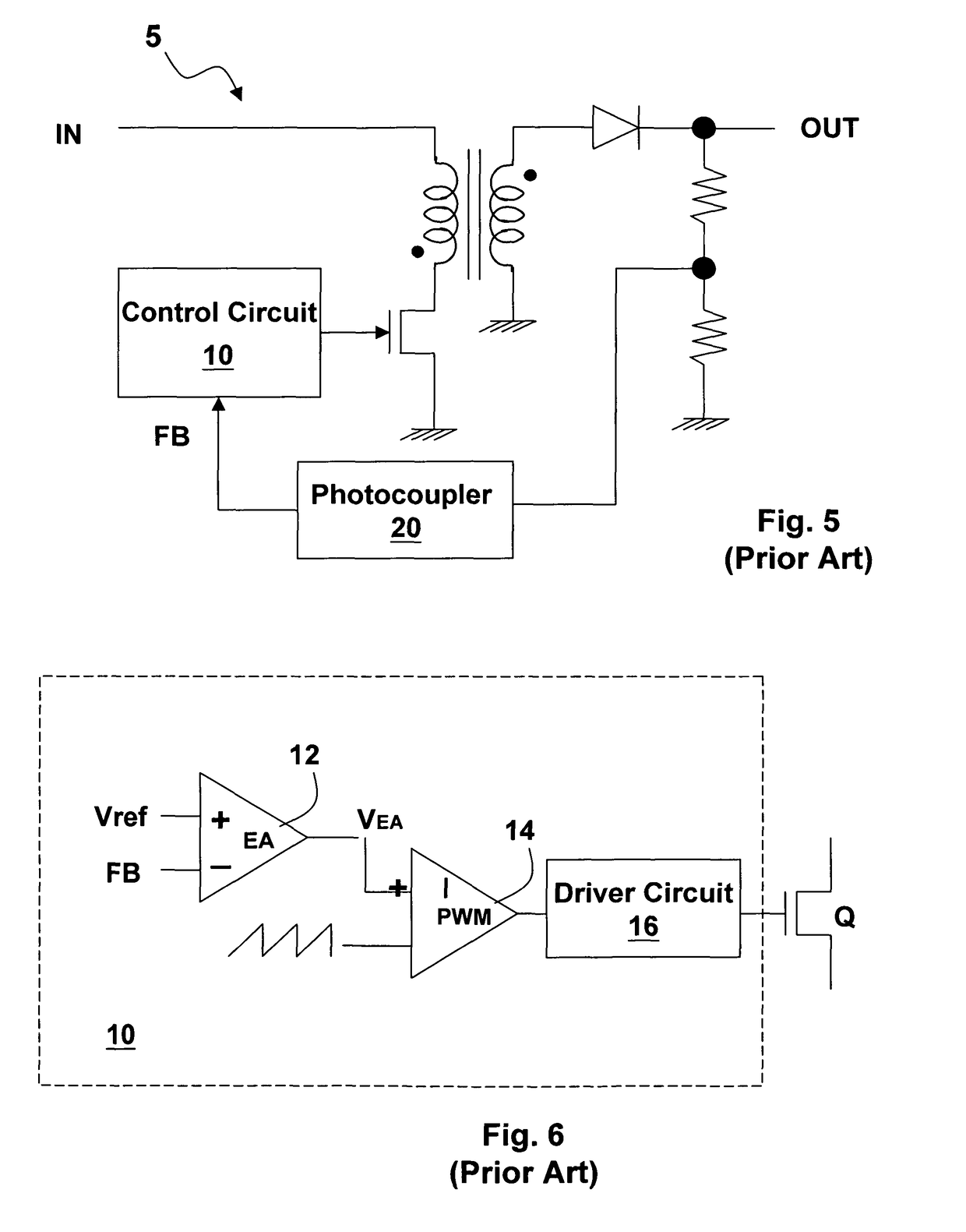
FIELD OF INVENTION[0001]The present invention relates to a power converter with improved line transient response, a control circuit for power converter, and a method for improving line transient.DESCRIPTION OF RELATED ART[0002]There are various types of power converters such as buck converter, boost converter, inverter converter, buck-boost converter, and fly back converter. FIG. 1 shows a conventional buck converter, which comprises two power transistor switches Q1 and Q2 controlled by a control circuit 10. The control circuit 10 generates switch control signals according to a feedback voltage signal FB extracted from an output terminal; the switch control signals control the operation of the transistors Q1 and Q2 so as to transmit power from the input IN to the output OUT. FIG. 2 shows a boost converter 2; FIG. 3 shows an inverter converter 3; FIG. 4 shows a buck-boost converter 4; FIG. 5 shows a fly back converter 5. Despite the foregoing circuits have different circuit structure...

Claims


Application Information

Patent Timeline
Patent Type & Authority Patents(United States)
IPC IPC(8): G05F5/00
CPCH02M3/156H02M2001/0022H02M3/1582H02M1/0022
Inventor JAN, CHUEH-KUEILIN, SHUI-MU
Owner RICHTEK TECH
Learn More