Magnet sensor arrangement for sensing the movement of element moving in linear or rotary fashion

a technology of magnetic sensor and linear or rotary motion, applied in the field of magnetic sensor arrangement, can solve the problem of large offset and relatively weak signal, and achieve the effect of minimizing the offset of the output signal of the sensor elemen

Inactive Publication Date: 2012-02-21
ROBERT BOSCH GMBH
View PDF15 Cites 64 Cited by
  • Summary
  • Abstract
  • Description
  • Claims
  • Application Information

AI Technical Summary

Benefits of technology

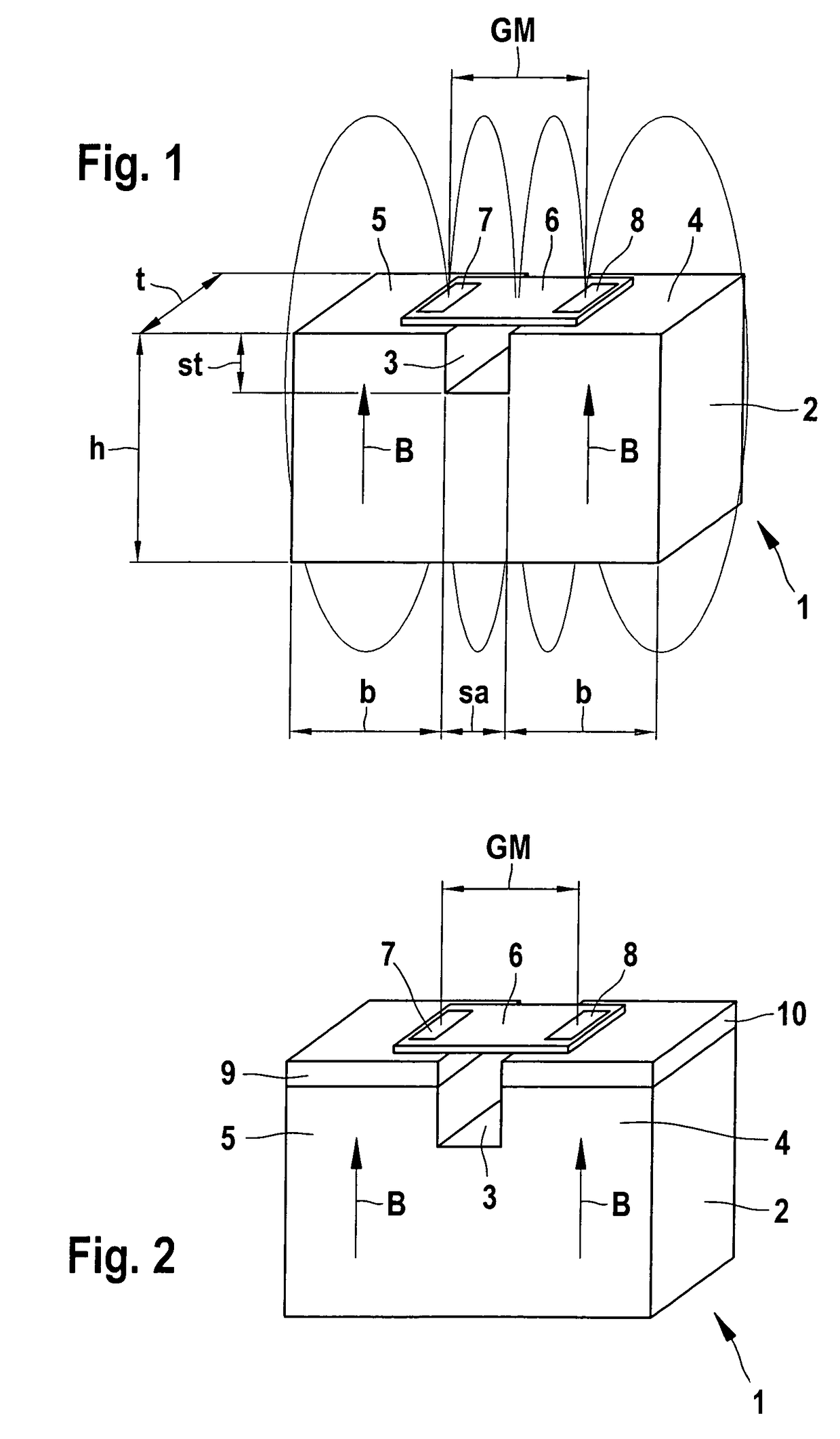
[0008]In a modification of a magnetic sensor arrangement of the type mentioned at the beginning, the magnetic sensor arrangement according to the present invention has two sensor elements in a gradiometer arrangement, each of which is associated with one of two magnetic regions spaced a predetermined distance apart from each other in a permanent gap magnet. In terms of their dimensions, the gap width, the gap shape, the gap depth, and their position in relation to the sensor elements, these regions and the entire permanent gap magnet are advantageously positioned so as to minimize the offset of the output signal of the sensor elements in the gradiometer arrangement.
[0009]The present invention consequently makes it possible to optimize the design of a magnetic circuit that generates a working field for a sensor, which operates using the gradiometer principle, i.e. through detection of the field gradients, thus enabling an offset-free operation of the sensor when variations in the magnetic field are generated by moving transmitter elements, in particular ferromagnetic gears. To that end, the magnetic circuit is composed of two regions whose fields overlap so that the so-called “in-plane” components of the resulting magnetic field and the working field in the sensitive x-direction in XMR sensors, are reduced at the gradiometer positions to such an extent that they vary around the zero position due to the influence of the passive transmitter elements. It is thus possible to detect very weak signals in an offset-free fashion.
[0010]This is particularly advantageous with very sensitive magnetoresistive XMR sensors, which should cover as large a working range as possible without an offset correction, i.e. from very high to very low field strengths. In comparison to magnetic circuits that are comprised of a plurality of separate components, the single-component gap magnet according to the present invention is simpler in design and less expensive to manufacture.
[0011]In a particularly advantageous fashion, the gap of the gap magnet has a wedge-shaped contour or one that is curved in some other way. This gap shape reduces the offset minimization in the magnetic circuit not only at the two gradiometer positions, but instead, spreads the reduction over a wide region parallel to the surface of the magnet or to a flux-conducting plate. This results in significantly reduced position change requirements in the gradiometer position of the XMR sensor element with regard to the magnetic arrangement.
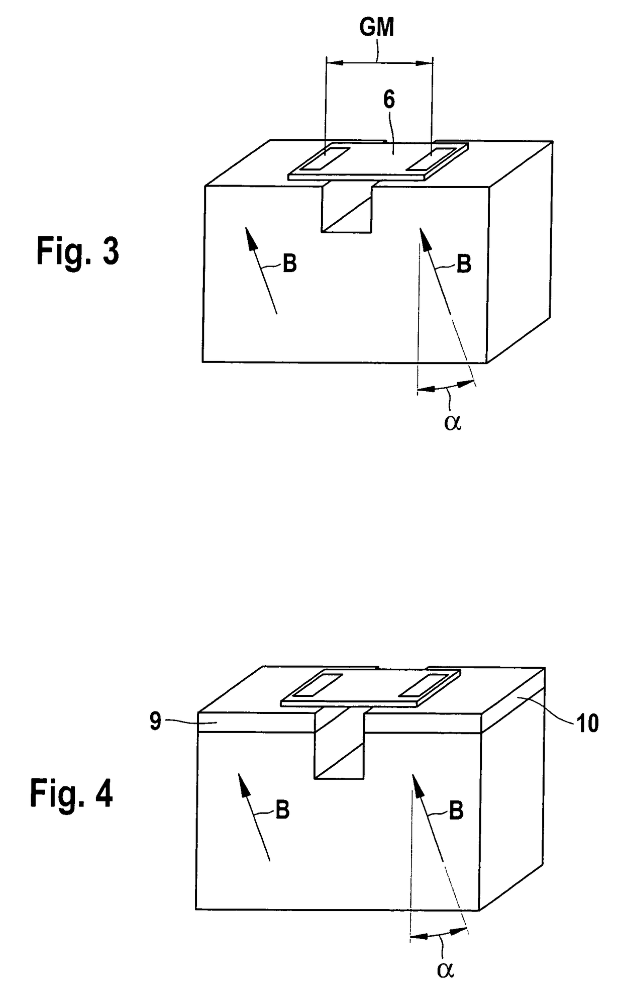
[0013]In an advantageous embodiment form, flux-conducting plates functioning as homogenization plates are positioned between the sensor elements and the magnetic regions. This homogenizes the field in the plane of the sensor elements and reduces the positioning precision of the sensor elements in relation to the magnetic pair required for offset-free operation.
[0014]According to another embodiment form, it is also advantageous if the magnetization of the regions is rotated by a predetermined angle α from its longitudinal direction oriented toward the sensor elements.

Problems solved by technology

But it is no longer possible in this case to carry out a balancing of the previously used magnet so that the offset can be eliminated at both locations of the sensor elements of the gradiometer arrangement; an electronic balancing is in principle possible, but in this case, a large offset yields a relatively weak signal.

Method used


Image

  • Magnet sensor arrangement for sensing the movement of element moving in linear or rotary fashion
  • Magnet sensor arrangement for sensing the movement of element moving in linear or rotary fashion
  • Magnet sensor arrangement for sensing the movement of element moving in linear or rotary fashion

Examples


Embodiment Construction

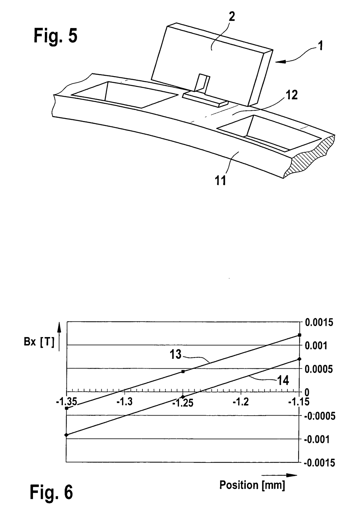
[0032]FIG. 1 is a schematic depiction of a magnetic sensor arrangement 1, which has a permanent magnet embodied in the form of a gap magnet 2. On both sides of a gap 3, this gap magnet 2 has regions 4 and 5 that are magnetized in the same direction, whose respective magnetic field B is aligned with the field lines shown here extending in the direction of a sensor 6. The sensor 6 in this case is embodied in the form of an XMR sensor and has two magnetoresistive sensor elements 7 and 8. The sensor elements 7 and 8 are shown in a gradiometer arrangement—which has the gradiometer distance GM—and detect the changes in the respective field gradients that are caused, for example, by a metallic transmitter element, e.g. a gear depicted in FIG. 5, being moved past the magnetic sensor arrangement 1.

[0033]The optimal operating point of the sensor 6 is set via the distance of the individual magnets 4 and 5, defined by the gap width sa and the gap depth st in relation to each other, and can be a...


PUM


Abstract

A magnetic sensor arrangement (1), having magnetically sensitive sensor elements (7, 8) whose electrical properties are changeable as a function of a magnetic field that a moving, passive transmitter element (11) is able to influence. The magnetic sensor arrangement (1) has two sensor elements (7, 8) in a gradiometer arrangement that are each respectively associated with one of two magnetic regions (4, 5) of a permanent magnet embodied in the form of a gap magnet (2; 20; 23), which regions are spaced apart from each other by a predetermined distance (sa). The regions (4, 5) and the gap magnet (2; 20; 23)—in terms of the for example wedge-shaped embodiment, the dimensions (h, b, t), the gap width (sa), the gap depth (st), and their positions in relation to the sensor elements (7, 8)—are situated so as to minimize the offset of the output signal of the sensor elements (7, 8) in the gradiometer arrangement.

Description

CROSS-REFERENCE TO RELATED APPLICATIONS[0001]The invention described and claimed hereinbelow is also described in German Patent Applications DE 10 2004 0118 10.8 filed on Mar. 11, 2004 and DE 10 2004 0635 39.0 filed on Dec. 30, 2004. These German Patent Applications provides the basis for a claim of priority of invention under 35 U.S.C. 119(a)-(d).BACKGROUND OF THE INVENTION[0002]The present invention relates to a magnetic sensor arrangement, in particular for sensing the movement of elements moved in linear or rotary fashion.[0003]It is intrinsically known that magnetic field-sensitive sensors are used in many areas of use in which a contact-free detection of a movement is desired. This motion can be rotary or linear. It is necessary to draw a distinction here between two different basic measurement principles. On the one hand, attaching one or more active elements in the form of magnetic dipoles to the element to be detected makes it possible to determine the movement directly by ...

Claims


Application Information

Patent Timeline
Patent Type & Authority Patents(United States)
IPC IPC(8): G01B7/30G01D5/14G01D5/16G01R33/022
CPCG01D5/147
Inventor RETTIG, RASMUSBAUER, CHRISTIANVOGELGESANG, BIRGIT
Owner ROBERT BOSCH GMBH
Why Eureka
Try Eureka