Antenna system for tracking satellite

a satellite and antenna technology, applied in the direction of antennas, antenna details, antenna adaptation in movable bodies, etc., can solve the problems of inability to precisely track the satellite, increase the production cost of the system, and the structural limitation of the conventional antenna system that cannot appropriately cope with the

Inactive Publication Date: 2012-02-21
ELECTRONICS & TELECOMM RES INST
View PDF17 Cites 18 Cited by
  • Summary
  • Abstract
  • Description
  • Claims
  • Application Information

AI Technical Summary

Benefits of technology

[0005]It is, therefore, an object of the present invention to provide a satellite tracking antenna system which is capable of reducing the production cost, easily changing system performance when necessary, and improving accuracy of satellite tracking, by optimizing functions and performance of signal power transmission and reception and mechanical satellite tracking through efficient implementation of components included in the antenna system.Technical Solution
[0010]Moreover, it is preferred that the control unit includes a sensor unit having: a rate sensor for sensing an angular velocity to the motion of the antenna system; a tilt sensor for sensing a tilted declination of the antenna system; and a gyrocompass for measuring an azimuth by using a magnetic operating principle, the control unit transmitting the information sensed by the rate sensor, the tilt sensor and the gyrocompass to an antenna control unit which controls the azimuth motor, the elevation motor and the antenna rotating motor contained in the driving motor based on the information so that the antenna system can be oriented toward the satellite in real time.

Problems solved by technology

In general, when a conventional antenna system for tracking a satellite performs electronic or semi-electronic satellite tracking, the production cost of the system is increased.
Further, since the antenna system performs only 2-axis control in azimuth and elevation directions, it cannot precisely track the satellite if a beam width of an antenna is narrow.
Therefore, the conventional antenna system has a structural limitation that cannot appropriately cope with a satellite polarization angle error generated by a position variation of a movable body on which it is mounted, and a satellite-oriented angle error generated by a latitude variation.
In such a case, however, there exists an inconvenience of making all the supplementary components mounted on the movable body on which the antenna system is mounted.

Method used


Image

  • Antenna system for tracking satellite
  • Antenna system for tracking satellite
  • Antenna system for tracking satellite

Examples


Embodiment Construction

[0019]Hereinafter, a satellite tracking antenna system in accordance with a preferred embodiment of the present invention will be set forth in detail with reference to the accompanying drawings.

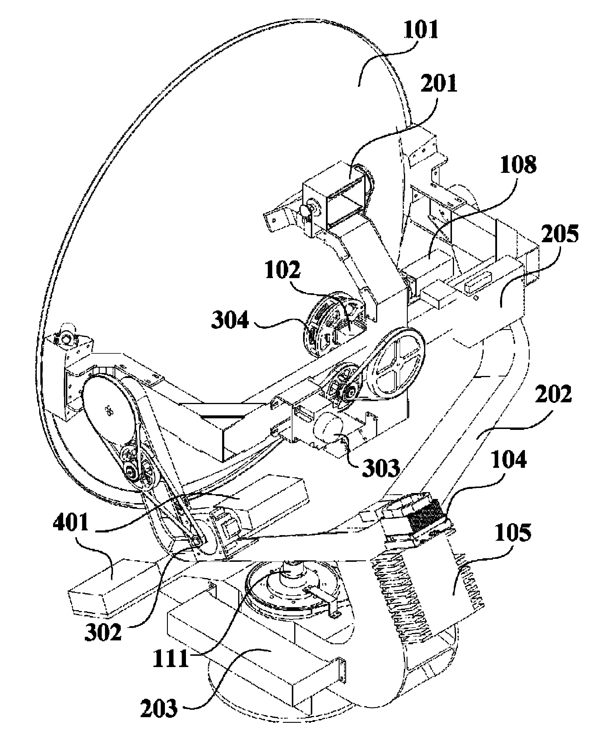
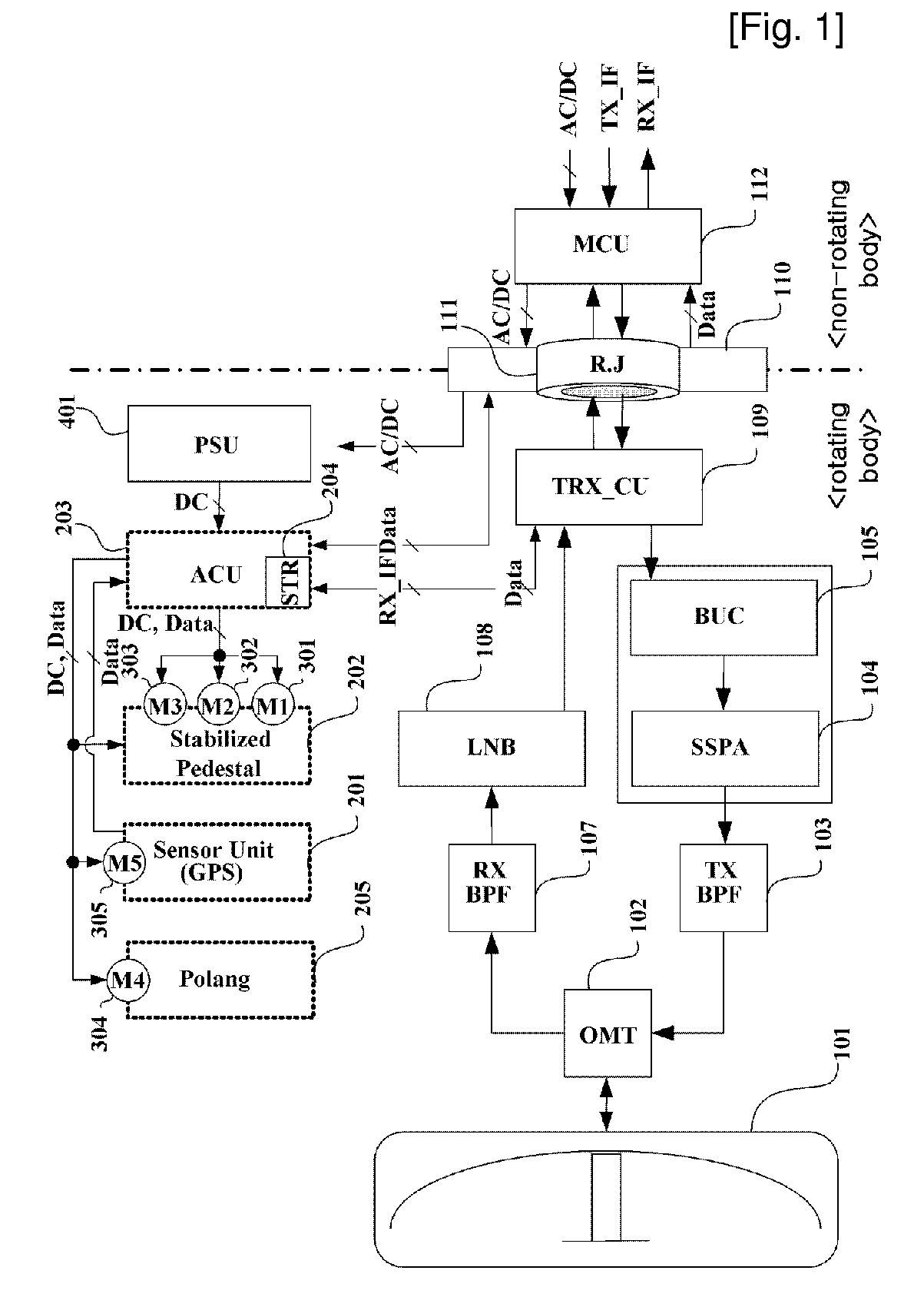
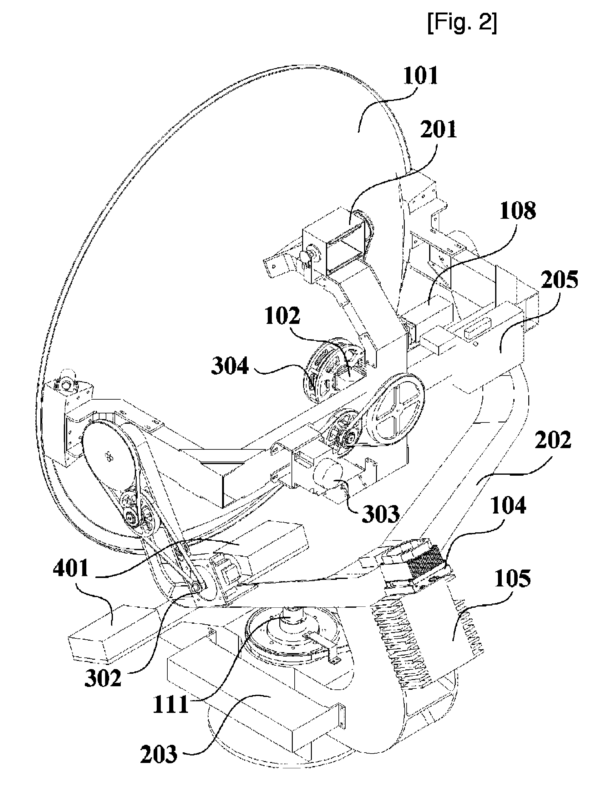
[0020]FIGS. 1 through 4 are structural views illustrating an antenna system for tracking a satellite in accordance with the present invention. That is, FIG. 1 is a structural view illustrating the antenna system for tracking the satellite, FIG. 2 is a perspective view illustrating the rear left side of the antenna system for tracking the satellite, FIG. 3 is a perspective view illustrating the rear right side of the antenna system for tracking the satellite, and FIG. 4 is a cross-sectional view illustrating the rear portion of the antenna system for tracking the satellite.

[0021]Referring to FIG. 1, the antenna system for tracking the satellite according to the invention basically includes a fixed body (non-rotating body) for transmitting and receiving communication and broadcasting signals to...


PUM


Abstract

Provided is an antenna system for tracking a satellite which includes a fixed body and a rotating body. The antenna system includes a transmitting / receiving unit having a transmitting channel and a receiving channel for signal power, a driving unit for enabling mechanical motion of the rotating body for satellite tracking, and a control unit for monitoring and controlling the operation of the driving unit. Accordingly, the various kinds of the components of the antenna system mounted and operated on the movable body can be minimized and the output of the transmitted signal required in the antenna system can be simply replaced, thereby simplifying the configuration of the system and reducing the production cost of the system. In addition, the STR having the tracking signal processing function in the digital mode as well as the general analog mode is mounted on the antenna system, thereby improving accuracy of satellite tracking. Moreover, the posture of the antenna system can be stably maintained regardless of the motion of the movable body in the moving environment by using the driving unit and the control unit which are designed for stably controlling the elevation, azimuth and antenna rotating angle, thereby improving communication performance that is the intrinsic object of the antenna system.

Description

TECHNICAL FIELD[0001]The present invention relates to an antenna system for tracking a satellite; and, more particularly, to a satellite tracking antenna system which is capable of reducing the production cost, easily changing system performance when necessary, and improving accuracy of satellite tracking by optimizing functions and performance of signal power transmission and reception and mechanical satellite tracking through efficient implementation of components included in the antenna system.BACKGROUND ART[0002]In general, when a conventional antenna system for tracking a satellite performs electronic or semi-electronic satellite tracking, the production cost of the system is increased. Further, since the antenna system performs only 2-axis control in azimuth and elevation directions, it cannot precisely track the satellite if a beam width of an antenna is narrow.[0003]In addition, the conventional antenna system performs simple 3-axis control even when it carries out mechanica...

Claims


Application Information

Patent Timeline
Patent Type & Authority Patents(United States)
IPC IPC(8): H01Q3/00
CPCH01Q1/1257H01Q1/288H01Q3/08H01Q19/10H01Q1/27
Inventor JUNG, YOUNG-BAEEOM, SOON-YOUNGYUN, JAE-SEUNGSON, SEONG-HOJEON, SOON-IKKIM, CHANG-JOO
Owner ELECTRONICS & TELECOMM RES INST
Why Eureka
Try Eureka