
System, module, and method for illuminating a target on an aircraft windshield

a technology of aircraft windshield and target, applied in the field of system, module and method of illuminating a target on an aircraft windshield, can solve the problems of difficult for pilots to determine where to look outside of aircraft to detect or locate runways and/or runway environment, and the lateral or horizontal angle through which the pilot must steer his or her gaze is not easily discernable, so as to enhance the pilot's situational awareness of the runway environment and/or other aircraft traffi

Active Publication Date: 2012-02-21
ROCKWELL COLLINS INC
View PDF3 Cites 44 Cited by
  • Summary
  • Abstract
  • Description
  • Claims
  • Application Information

AI Technical Summary

Benefits of technology

[0006]The embodiments disclosed herein present at least one novel and non-trivial system, module, and method for illuminating a target on an aircraft windshield corresponding to a three-dimensional position data outside of an aircraft. The use of a beam illuminating a target on the windshield may be used to enhance a pilot's Situational Awareness of the runway environment and / or other aircraft traffic, especially in flight conditions with low visibility and strong crosswinds.

Problems solved by technology

If executing the same approach in a condition where there is a more severe crosswind from the right, the aircraft may “crab” more severely to the right.
When the pilot arrives at a decision altitude or minimum decent altitude and looks up to view the outside scene through the windshield, it becomes more difficult for the pilot to determine where to look outside of aircraft to detect or locate the runway and / or the runway environment.
Even though the pilot may know of the general location, the lateral or horizontal angle through which the pilot must steer his or her gaze is not easily discernable from the image presented on a HDD unit given the minification caused by the Field of View.
Although the relationship between the runway and heading symbols may provide a cue to the pilot where to look for the runway environment, there may be a potential for confusion.
For example, heading symbols would appear to the right of the runway, but the pilot would have to look to the left, possibly making it more difficult for the pilot to locate the runway and / or the runway environment as he or she transitions from looking head-down to looking head-up.

Method used


Image

  • System, module, and method for illuminating a target on an aircraft windshield
  • System, module, and method for illuminating a target on an aircraft windshield
  • System, module, and method for illuminating a target on an aircraft windshield

Examples


Embodiment Construction

[0023]In the following description, several specific details are presented to provide a thorough understanding of embodiments of the invention. One skilled in the relevant art will recognize, however, that the invention can be practiced without one or more of the specific details, or in combination with other components, etc. In other instances, well-known implementations or operations are not shown or described in detail to avoid obscuring aspects of various embodiments of the invention.

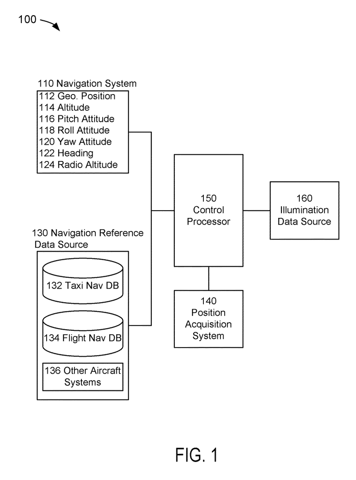
[0024]FIG. 1 depicts a block diagram of an aircraft windshield target illumination system 100 suitable for implementation of the techniques described herein. The aircraft windshield target illumination system 100 of an embodiment of FIG. 1 includes navigation system 110, a navigation reference data source 130, a position acquisition system 140, a control processor 150, and an illumination source 160.

[0025]In an embodiment of FIG. 1, navigation system 110 comprises the system or systems that could pr...


PUM


Abstract

A present novel and non-trivial system, module, and method for illuminating a target on an aircraft windshield corresponding to a three-dimensional location outside of an aircraft. Navigation data and three-dimensional location data are provided to a control processor; the navigation data may comprise aircraft position, heading, and pitch, roll, and yaw attitudes, and the three-dimensional location data may comprise a runway reference point. After an external target angle and track angle are determined, control data may be generated as a function of pitch, roll and / or yaw attitudes, glide path angle, track angle, and cockpit references originating from a design eye position. Control data may comprise data representative of vertical and / or lateral measurements which position a beam on a windshield target. Then, the control data may be provided to an illumination source for positioning a beam on the windshield target in response to the control data.

Description

FIELD OF THE INVENTION[0001]This invention pertains generally to the field of providing flight cues or visual aids to the pilot of an aircraft.DESCRIPTION OF THE RELATED ART[0002]During an approach to a runway, the image of the scene outside the aircraft presented on a head-down display (“HDD”) unit is traditionally heading-referenced. That is, the heading of the aircraft determines the horizontal centering of the image. When a pilot is flying in instrument meteorological conditions, there is a point during the approach, e.g., reaching a decision altitude or minimum decent altitude, at which he or she must look up and decide whether he or she may continue the approach to landing or execute a missed approach. In a zero crosswind condition and assuming a straight-in approach is being performed, the pilot may look through the windshield directly ahead of the aircraft to locate the runway and / or the runway environment. In a zero crosswind condition, heading and track would align with on...

Claims


Application Information

Patent Timeline
IPC IPC(8): G09G5/00
CPCG01C21/00G02B27/01G02B2027/014
Inventor BARBER, SARAH
Owner ROCKWELL COLLINS INC
Learn More