Storage management method and management server

a storage management and server technology, applied in the field of storage management methods and management servers, can solve the problems the possibility of reducing the i/o performance of other applications using the storage device, and the new performance problem of another application, so as to achieve the effect of reducing the volume of the moved virtual machine, reducing the i/o burden on the storage device, and increasing the utilization of computer resources

Inactive Publication Date: 2012-02-21
HITACHI LTD
View PDF17 Cites 68 Cited by
  • Summary
  • Abstract
  • Description
  • Claims
  • Application Information

AI Technical Summary

Benefits of technology

[0008]A conventional server virtualization technology, when a performance problem occurs with a virtual machine, solves the problem without newly purchasing additional computer resources by moving the troubled virtual machine to another physical server. On the other hand, once the performance problem on the virtual machine is resolved, an I / O (Input / Output) volume to the storage device may increase. More specifically, when the virtual machine is moved from a physical server short of computer resources to a physical server with sufficient computer resources, the virtual machine that has been moved is now able to utilize more computer resources. Then, the I / O volume in the moved virtual machine is likely to increase. As a result, an I / O burden on the storage device also increases to more than a maximum I / O process capacity of the storage device, giving rise to a possibility of reducing an I / O performance of other application using that storage device. Since the conventional technology does not check in advance for a possible I / O performance reduction that can occur on the storage device side as a result of the relocation of the virtual machine, the solving of a performance problem for a certain application by relocating a virtual machine can induce a new performance problem with another application.
[0010]Allocating many computer resources to a virtual machine that has been relocated may increase the volume of processing executed by an application running on the virtual machine. As the volume of processing performed by the application increases, the I / O burden on the storage device used by the application may also increase. Further, an increase in the I / O burden on this storage device can cause the I / O burden on the storage device to exceed the maximum I / O process capacity, which in turn may degrade the I / O performance of other applications sharing the storage device in question and cause a performance problem. As described above, since the conventional technology allocates additional virtual resources to a virtual machine, other applications that share the storage device with the virtual machine may have a degraded I / O performance.

Problems solved by technology

As a result, an I / O burden on the storage device also increases to more than a maximum I / O process capacity of the storage device, giving rise to a possibility of reducing an I / O performance of other application using that storage device.
Since the conventional technology does not check in advance for a possible I / O performance reduction that can occur on the storage device side as a result of the relocation of the virtual machine, the solving of a performance problem for a certain application by relocating a virtual machine can induce a new performance problem with another application.
As the volume of processing performed by the application increases, the I / O burden on the storage device used by the application may also increase.
Further, an increase in the I / O burden on this storage device can cause the I / O burden on the storage device to exceed the maximum I / O process capacity, which in turn may degrade the I / O performance of other applications sharing the storage device in question and cause a performance problem.
As described above, since the conventional technology allocates additional virtual resources to a virtual machine, other applications that share the storage device with the virtual machine may have a degraded I / O performance.

Method used


Image

  • Storage management method and management server
  • Storage management method and management server
  • Storage management method and management server

Examples


Embodiment Construction

[0037]Next, a best mode of implementing this invention (referred to as an “embodiment”) will be described in detail by referring to the accompanying drawings as need arises.

[0038]In the storage management system described in the following embodiment, functions and details not essential to the present invention are omitted and thus the storage management system of this embodiment is simpler than a general one. This however in no way limits the range of application of this invention.

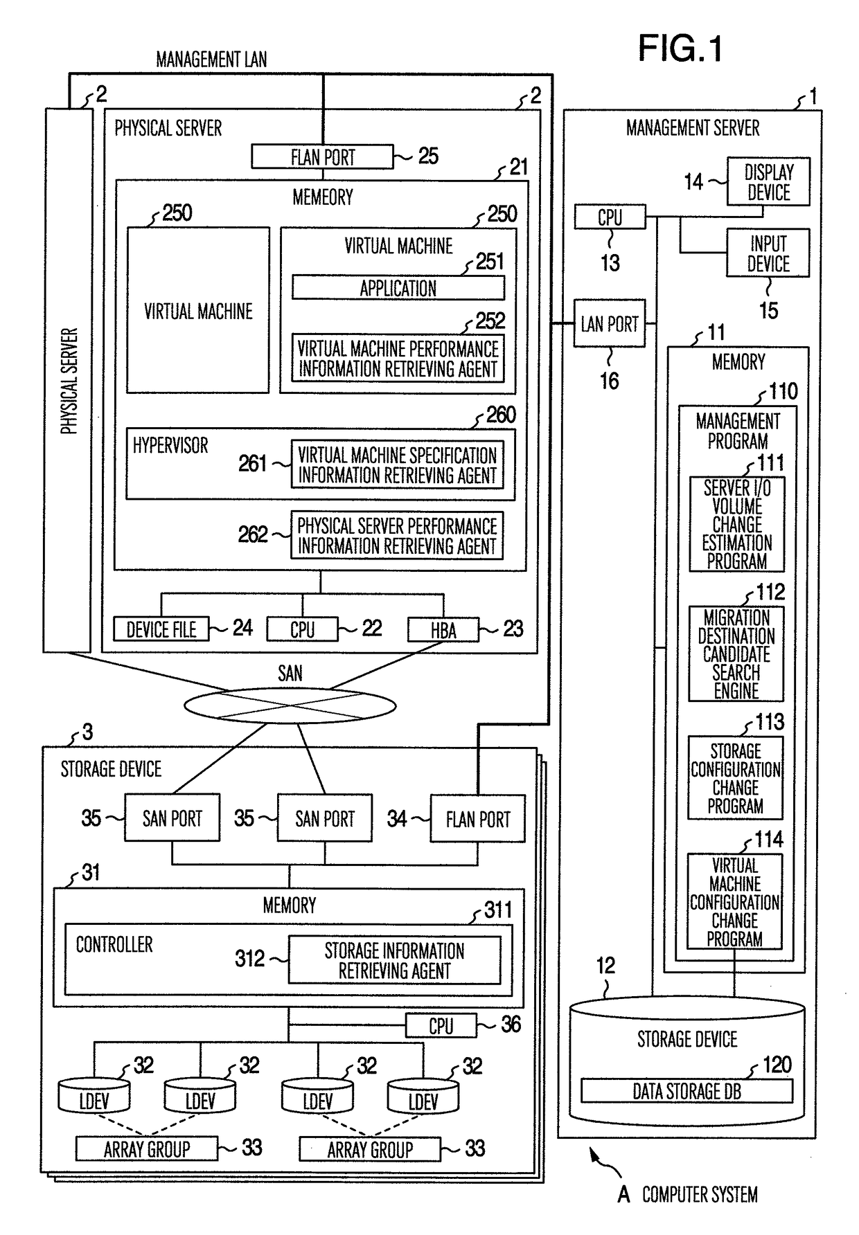
[0039]FIG. 1 shows an example configuration of a computer system according to this embodiment.

[0040]The computer system A has a plurality of storage devices 3, a plurality of physical servers 2 and a management server 1. The individual storage devices 3 and physical servers 2 are interconnected via SAN 4. The physical servers 2, the storage devices 3 and the management server 1 are interconnected via a management LAN (Local Area Network) 5. The connection between the physical servers 2 and SAN 4 is establi...


PUM


Abstract

A method for moving a virtual machine is provided which considers an input / output between array groups and virtual machines after being moved. The computer system includes a physical server executing the virtual machines, a storage device having array groups, and a management server that manages a link between the virtual machines and the array groups. The computer system is characterized in that an estimated I / O volume of the virtual machine after being moved is calculated and that, if the estimated I / O volume exceeds the maximum I / O volume of the array group connected to the moved virtual machine, a search is made to find an array group whose maximum I / O volume is smaller than the estimated I / O volume.

Description

INCORPORATION BY REFERENCE[0001]The present application claims priority from Japanese application JP2008-282267 filed on Oct. 31, 2008, the content of which is hereby incorporated by reference into this application.BACKGROUND OF THE INVENTION[0002]The present invention relates to a storage management method and a management server technology.[0003]With information technologies spreading in a variety of business fields, the number of physical servers and the volume of data corporations hold have been continuing to rise. Under this circumstance a spotlight is being focused on a server virtualization technology to collectively manage an increasing number of physical servers to reduce their number and on a collective management of storage based on the SAN (Storage Area Network). Behind this trend there is a growing number of corporations intent on solving such problems as an increase in power consumption and exhaust heat volume due to increased densities of physical server groups and st...

Claims


Application Information

Patent Timeline
Patent Type & Authority Patents(United States)
IPC IPC(8): G06F15/173
CPCG06F3/0626G06F3/0647G06F3/067G06F9/5077G06F9/45558G06F2009/45579G06F2009/45583G06F2009/4557
Inventor MATSUNAGA, NAOYUKIKUSAMA, TAKATOBENIYAMA, NOBUO
Owner HITACHI LTD
Why Eureka
Try Eureka