Combustion chamber of a combustion system

a combustion system and combustion chamber technology, applied in the direction of combustion types, machines/engines, lighting and heating apparatus, etc., can solve the problems of achieve the effect of avoiding damage to the support elements or the support structure, local increase or decrease of the cooling edge region, and increasing the service life of the combustion chamber

Inactive Publication Date: 2012-02-28
ANSALDO ENERGIA IP UK LTD
View PDF24 Cites 11 Cited by
  • Summary
  • Abstract
  • Description
  • Claims
  • Application Information

AI Technical Summary

Benefits of technology

[0006]The invention is based on the general idea of designing a heat shield, which has at least two segments, with internal cooling passages so that locally variable cooling inside a segment is possible. In general, each segment in this case has a liner element, which faces a combustion space, and a retaining device, wherein the liner element is directly exposed to the hot gas flow and is fastened on a support structure via a support element. On the other hand, the retaining device, the liner element and the support element are fixed on the support structure. On the edge side, each liner element has an edge region which fits under a flange region of the retaining device which forms it. In this case, the individual segments are arranged next to each other so that a gap for thermal expansion, which is open towards the combustion chamber and into which hot gas can penetrate, remains between the edges of two adjacent liner elements. Therefore, in the case of the combustion chamber according to the invention it is provided that the retaining device together with the support element forms a first cooling passage in which flows cooling gas for cooling the liner element. For cooling the edge regions of the liner elements which face the gap, the retaining device, in the region of its flange region, has through-openings through which cooling gas flows from the first cooling passage to the edge region which is to be cooled and, depending upon configuration of the through-openings, enables a locally increased or decreased cooling of the edge region. Since the liner elements in the region of the gap do not completely reach as far as the support element or the support structure, hot gas which has penetrated into the gap can lead to an impairment of, or damage to, the support elements or the support structure. In order to counteract this, the through-holes are provided, which enable a calculated guiding of cooling gas from the first cooling passage to the edge region to be cooled, and as a result creates a requirement-oriented, locally defined cooling. As a result of the locally adapted cooling according to the invention, damage to, or impairment of, the support elements or the support structure can be avoided and consequently the service life of the combustion chamber can be increased. At the same time, maintenance cost is reduced, and as a result, lowering the operating costs can be achieved.
[0007]In an advantageous embodiment of the solution according to the invention, a distance between two through-openings, and / or a diameter of the through-openings, is adapted to a local cooling requirement. In the case of a high cooling requirement, it is therefore conceivable that a relatively small distance between two adjacent through-openings is selected, and / or a relatively large diameter of the through-openings is selected, whereas in the case of a rather low cooling requirement a larger distance between two through-openings can be selected, or a smaller diameter of the through-openings can be selected. This individual adaptation allows a requirement-oriented cooling of locally variably temperature-stressed regions and as a result also allows an improvement of the efficiency of the turbine since there are no excessively cooled regions which unnecessarily cool the hot gas flow.
[0008]One embodiment, in which an inner liner element is provided between the support structure and the liner element, and which together with the support structure forms a second cooling passage, or in which the liner element together with the inner liner element forms a third cooling passage, is especially advantageous. Such splitting into a plurality of cooling passages inside the heat shield allows an even more accurate controlling of the cooling of the heat shield, wherein the cooling gas first flows through the regions which are to be cooled more intensely, and then, after proportionate warming up, cool the regions which are to be cooled less intensely. As a result of this, cooling which is especially effective and also adapted to the necessary cooling requirement in each case can be carried out.
[0009]In a further advantageous embodiment, the pressure in the second cooling passage is greater than in the first cooling passage, and in the first cooling passage the pressure is greater than in the third cooling passage. As a result of this pressure drop, a controllable cooling flow can be created which, on account of the pressure difference, flows automatically through regions which are to be cooled in each case, and as a result saves a costly controlling of the cooling flows. The pressure difference between the individual cooling passages in this case can be controlled via a flow cross section of connecting passages which connect the individual passages, as a result of which influence can be brought to bear on the flow velocity at the same time.

Problems solved by technology

Since the liner elements in the region of the gap do not completely reach as far as the support element or the support structure, hot gas which has penetrated into the gap can lead to an impairment of, or damage to, the support elements or the support structure.

Method used


Image

  • Combustion chamber of a combustion system
  • Combustion chamber of a combustion system
  • Combustion chamber of a combustion system

Examples


Embodiment Construction

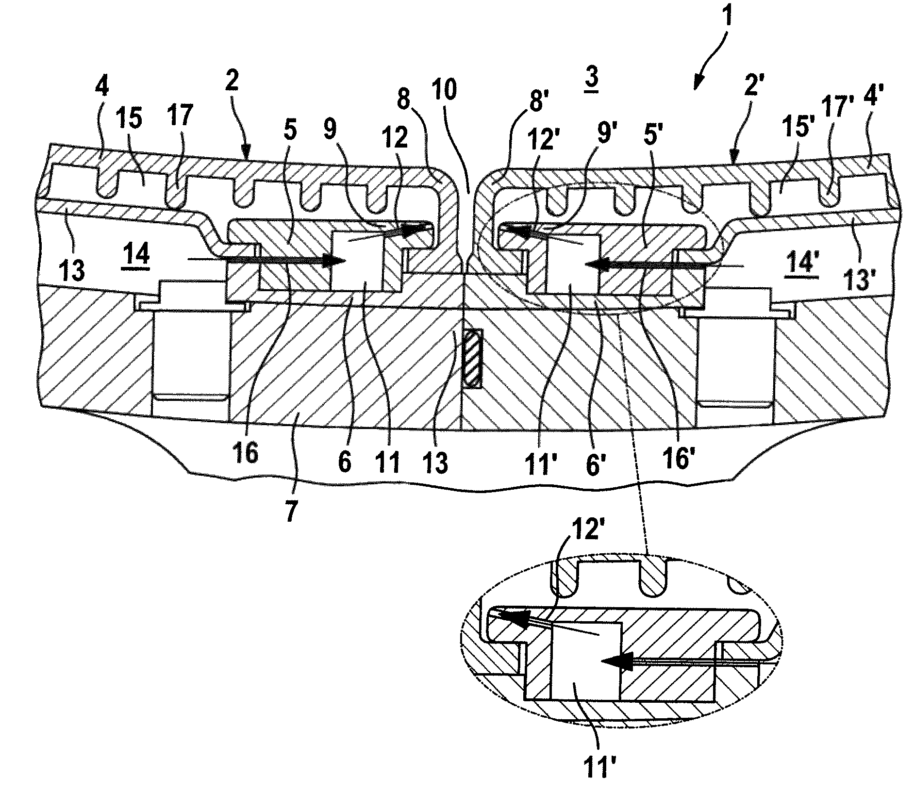
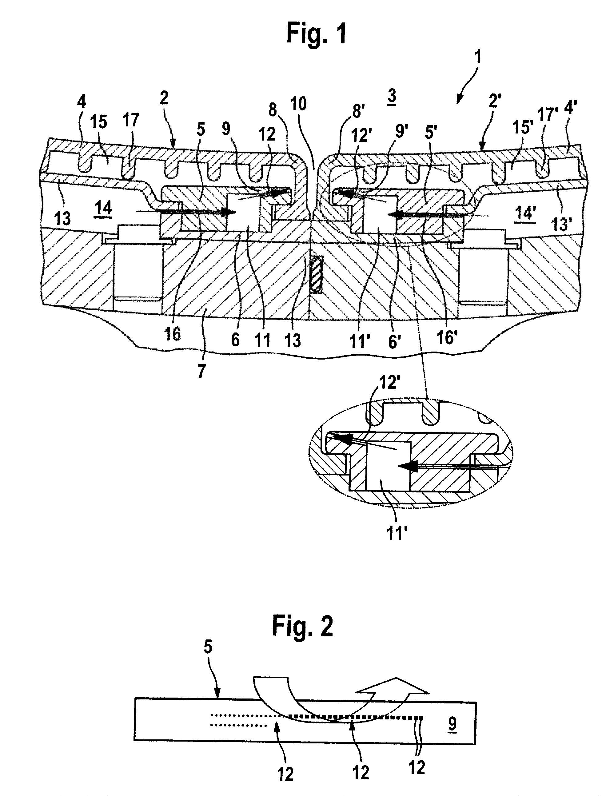
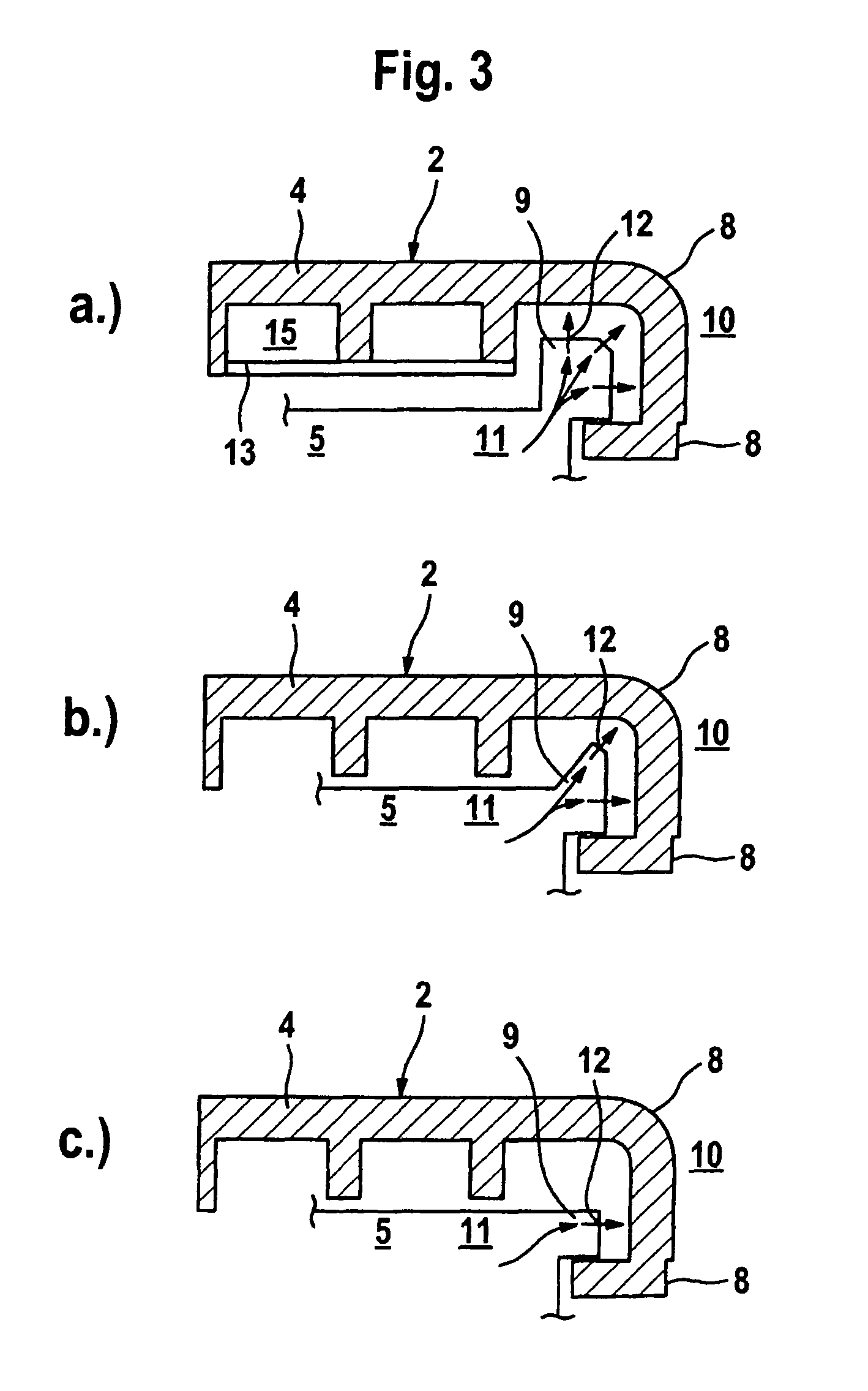
[0016]In accordance with FIG. 1, a sectional view through a combustion chamber wall of a combustion system, especially of a gas turbine, is shown, with a heat shield 1 which has at least two segments 2 and 2′ which are arranged next to each other. Each of the two segments 2 and 2′ furthermore has a liner element 4, which faces a combustion space 3, and a retaining device 5. The liner element 4 in this case is formed from a material which is not affected by heat since it is in direct contact with hot gases which are present in the combustion space 3. The two liner elements 4 and 4′ are fixed on a support structure 7 via a support element 6, wherein the retaining device 5 fixes both the liner element 4 and the support element 6 on the support structure 7. In this case, fastening of the liner element 4 on the retaining device 5 is carried out by means of an edge region 8 which is formed on the liner element 4 and fits in an undercut-like manner under a flange region 9 which is formed b...


PUM


Abstract

A combustion chamber of a combustion system has a combustion space, a support structure, a support element, and a heat shield. The heat shield has at least two segments, and each segment includes a liner element facing the combustion space and has an edge region, a gap communicating with the combustion space being formed between edge regions of adjacent segments, and a retaining device. The retaining device fixes the respective liner element on the support structure via the support element and forms a flange region that fits over the edge region of the respective liner element. The retaining device forms a first cooling passage with the support element and has at least one through-opening in the flange region. A cooling gas flows through the through.opening from the first cooling passage to the edge region.

Description

[0001]This application is a continuation of International Patent Application No. PCT / EP2007 / 056878, filed on Jul. 6, 2007, which claims priority to Swiss Patent Application No. CH 01259 / 06, filed on Aug. 7, 2006. The entire disclosure of both applications is incorporated by reference herein.[0002]The invention refers to a combustion chamber of a combustion system, especially of a gas turbine, with a heat shield which has at least two segments.BACKGROUND[0003]Combustion chambers of a combustion system, for example of a gas turbine, are customarily equipped with a heat shield which protects a subjacent support structure against a direct contact with a hot gas flow. Depending upon position in the combustion chamber, or with regard to the hot gas flow, the heat shield, or individual segments of it, in this case is or are exposed to a variable temperature stress.[0004]A nozzle segment for use in a gas turbine is known from EP 1 143 109 B1 and comprises a side wall, which extends essentia...

Claims


Application Information

Patent Timeline
Patent Type & Authority Patents(United States)
IPC IPC(8): F02C7/20
CPCF23M5/00F23R3/002
Inventor TSCHIRREN, STEFANBURRI, DANIELABDON, ANDREASSTEINBACH, CHRISTIAN
Owner ANSALDO ENERGIA IP UK LTD
Why Eureka
Try Eureka