Ear-mounted lenticular acoustic reflector

a technology of lenticular acoustic reflector and lenticular lens, which is applied in the field of ear-mounted reflective acoustic lens, can solve the problems of sound waves, the prior art devices that cannot overcome the problems of such devices, and the inability to provide lenticular accuracy to its reflections, so as to achieve phase-coherence and accurate sonic image relationships.

Active Publication Date: 2012-02-28
RILEY MICHAEL D
View PDF9 Cites 22 Cited by
  • Summary
  • Abstract
  • Description
  • Claims
  • Application Information

AI Technical Summary

Benefits of technology

[0014]Accordingly, it is an object of this invention to provide a non-electronic acoustic device that mechanically intersects more sound wave radiation than can the human ear alone, and that reflects and concentrates those sound waves into either one or both of the user's ear or ears in...

Problems solved by technology

344526, issued Nov. 23, 1921 and U.S. Pat. No. 3,938,616, issued Feb. 17, 1976 to Brownfield, can cause sound waves to acquire these kinds of distortions, by causing excessive reflections and resonances within the amplifying device itself.“Testing of active transducers (stereo headphones) used in close proximity to the ear has revealed that “ .
The geometry of the cavities coupling the earphone to the ear drum, which is affected by such factors as the position...

Method used


Image

  • Ear-mounted lenticular acoustic reflector
  • Ear-mounted lenticular acoustic reflector
  • Ear-mounted lenticular acoustic reflector

Examples


Embodiment Construction

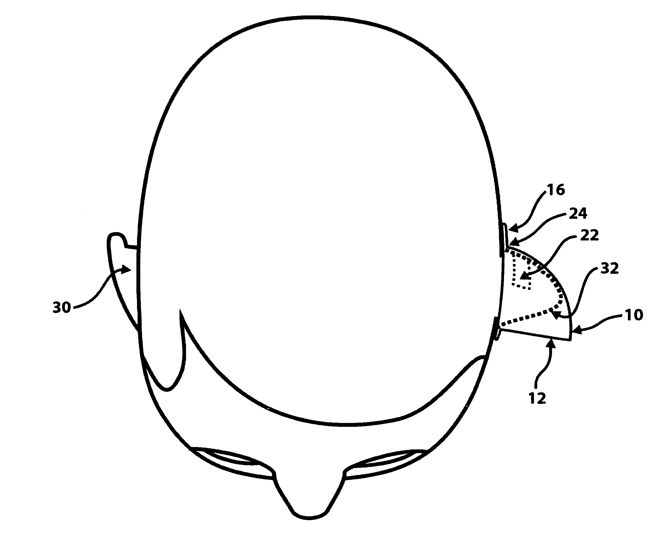
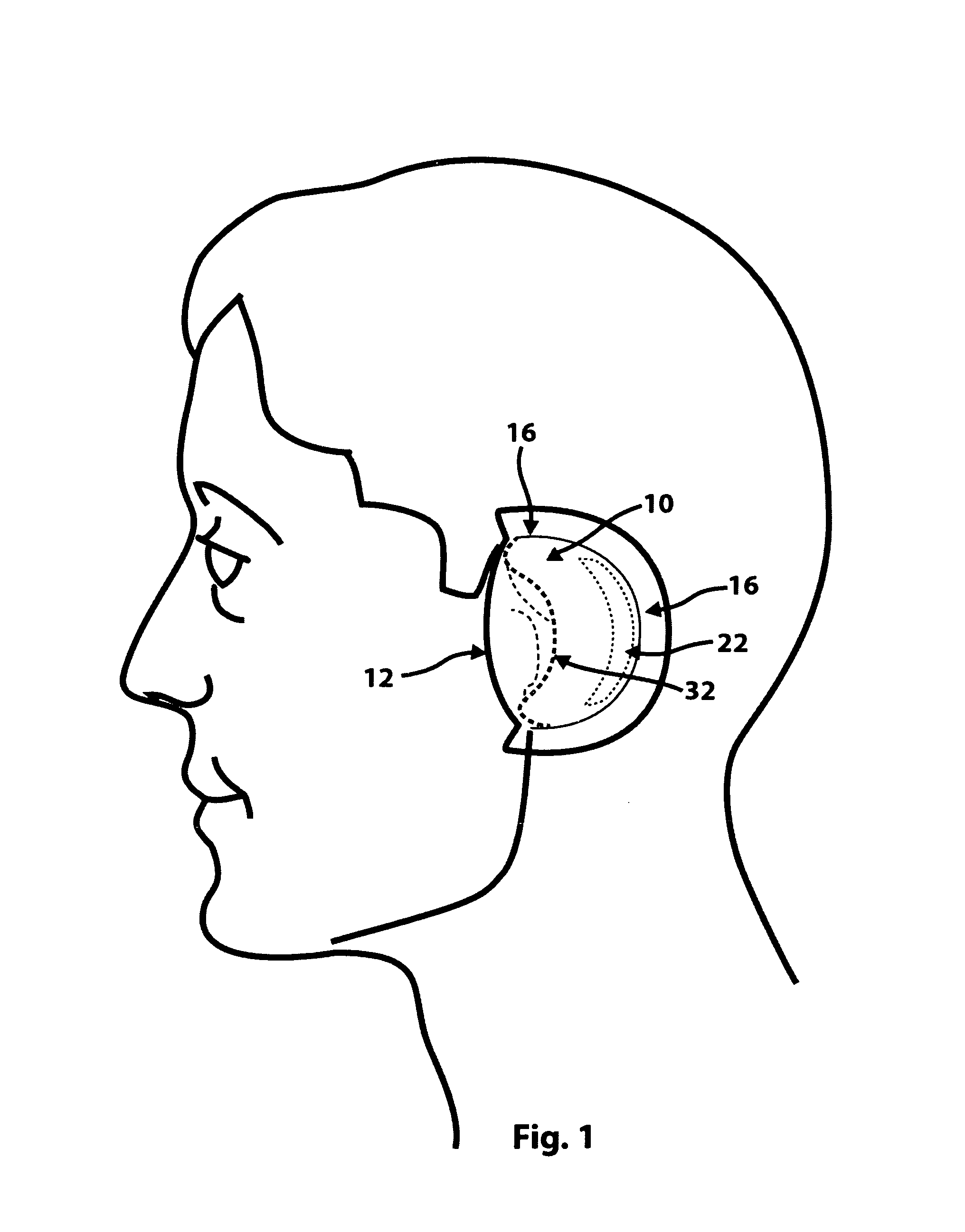
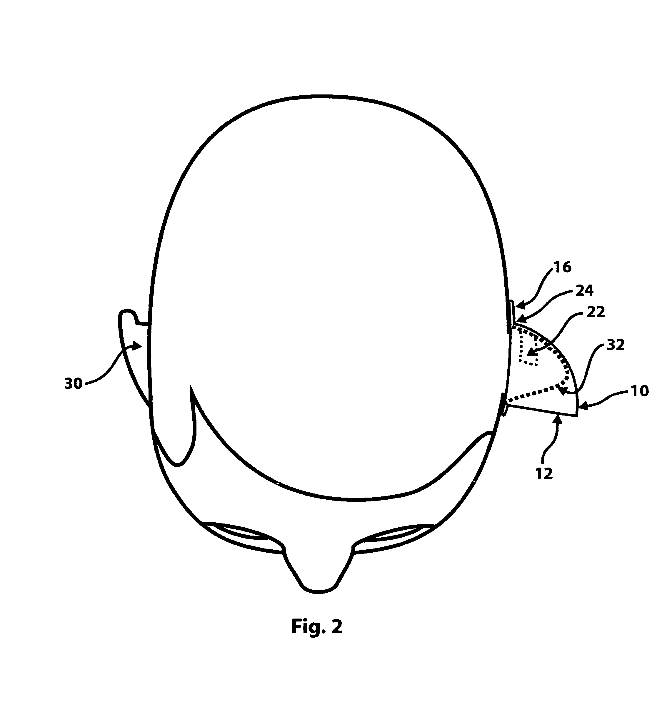
[0040]We turn now to the drawings on a descriptive basis, with similar reference characters denoting similar elements in all of the several views. FIGS. 1 through 2 illustrate an oblate spherical lune or diangle shaped paraboloid acoustic reflector 10 formed of a relatively thin plastic film as it would appear from the side and above when worn on a user's left ear, with all of the objects located inside the reflector shown with dotted outlines, and with the optional adhesive strip 22 and its protective covering strip 23 shown on the back side of the interior of the reflector 10. FIGS. 3 through 6 illustrate the acoustic reflector 10 as it would appear when not being worn by a user, shown without and with the optional interior adhesive strip 22, from both the outside facing left and from the front. FIGS. 7 through 8 illustrate a means whereby the amount of inward pressure against the top and bottom of the pinna 32 of a prospective wearer that is needed to produce the amount of outwar...


PUM


Abstract

The present invention pertains to an ear-mountable, paraboloid-shaped reflective acoustic lens which can be used to enhance a user's perception of the sounds from a source the user faces. The lens mechanically collects and naturally amplifies the airborne acoustic information from the sound source. The lens uses both the wearer's external ear as well as the interior face of an acoustic lens to coherently reflect increased amounts of sound from the source into the ear canal of a user who wears the lightweight, deformable lens. All sections of the lens meet the head of the user at an obtuse angle. The lens is held in place around the user's ear by the inward pressure of the lens pushing against the outside of the user's pinna. Adherence of the device to the ear of the wearer can be increased by an adhesive strip on the interior face of the lens.

Description

TECHNICAL FIELD[0001]The present invention pertains to an ear-mountable reflective acoustic lens with a shape that approximates an oblate spherical-section lune or diangle paraboloid which can be used to enhance a user's perception of the sounds generated by a sound source which the user faces. The invention's lens does so by mechanically collecting and more naturally amplifying the airborne acoustic information transmitted in the user's direction from the sound source. The lens uses both a larger portion of the interior surface of the wearer's external ear (pinna or auricle and concha) as well as the interior face of an acoustic lens to intercept and coherently reflect increased amounts of sound waves radiated by the sound source into the ear canal of a user who wears the invention's lightweight and deformable lens. The base of all sections of the lens intersects the head of the user at an obtuse angle at all points. The lens is held firmly but comfortably in place around either on...

Claims


Application Information

Patent Timeline
IPC IPC(8): H04R25/00
CPCA61F11/008A61F11/30
Inventor RILEY, MICHAEL D.
Owner RILEY MICHAEL D
Why Eureka
Try Eureka