Method for discharging liquid material, method for manufacturing color filter, and method for manufacturing organic EL element

a technology of liquid material and filter, which is applied in the direction of liquid/solution decomposition chemical coating, superimposed coating process, instruments, etc., can solve the problems of color irregularities and discrepancies in the amount of droplets discharged from the plurality of nozzles, and achieve good yield rate and prevent the effect of droplets discharged in the scanning direction

Active Publication Date: 2012-02-28
TOKYO ELECTRON LTD
View PDF6 Cites 22 Cited by
  • Summary
  • Abstract
  • Description
  • Claims
  • Application Information

AI Technical Summary

Benefits of technology

[0013]According to this method, during the scanning of the plurality of nozzles and the discharge object, droplets are discharged at a different discharge timing from adjacent nozzles associated with film formation areas from among a nozzle row composed of a plurality of nozzles. Since the combination of drive waveforms of different discharge timings applied to the energy generation element of adjacent nozzles is changed at least once, it is possible to prevent droplets having discharge amount disparities from being discharged continuously in the scanning direction as a result of nonuniformity in the discharge characteristics between adjacent nozzles. Consequently, at least electrical crosstalk in the nozzle row can be avoided, and it is possible to disperse disparities in the amount of droplets discharged in the scanning direction that occur along with the selection of the combination of drive waveforms of different discharge timings. Specifically, streaked discharge irregularities in the scanning direction can be reduced.
[0033]According to this method, disparities in the amount of droplets discharged in the scanning direction can be prevented, problems with light-emitting irregularities or brightness irregularities caused by streaked discharge irregularities can be reduced, and organic EL elements can be manufactured at a good yield rate.

Problems solved by technology

However, in practice there have been discrepancies between nozzles in regard to the amount of droplets discharged from the plurality of nozzles in the droplet discharge heads.
When these discrepancies are large, irregularities occur in the thin film formed after discharge, and if the product is a color filter, for example, the problem of color irregularities has been encountered.

Method used


Image

  • Method for discharging liquid material, method for manufacturing color filter, and method for manufacturing organic EL element
  • Method for discharging liquid material, method for manufacturing color filter, and method for manufacturing organic EL element
  • Method for discharging liquid material, method for manufacturing color filter, and method for manufacturing organic EL element

Examples


first embodiment

Droplet Discharge Device

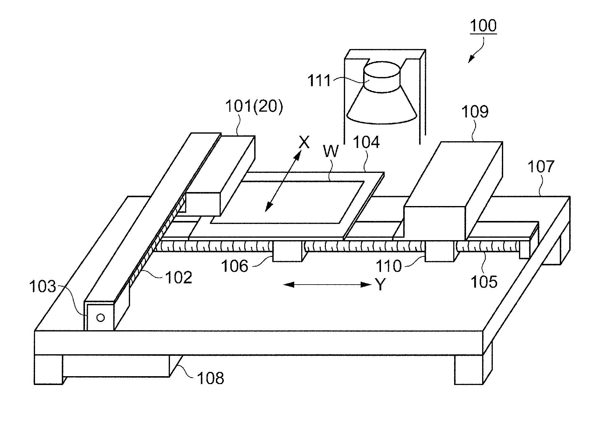
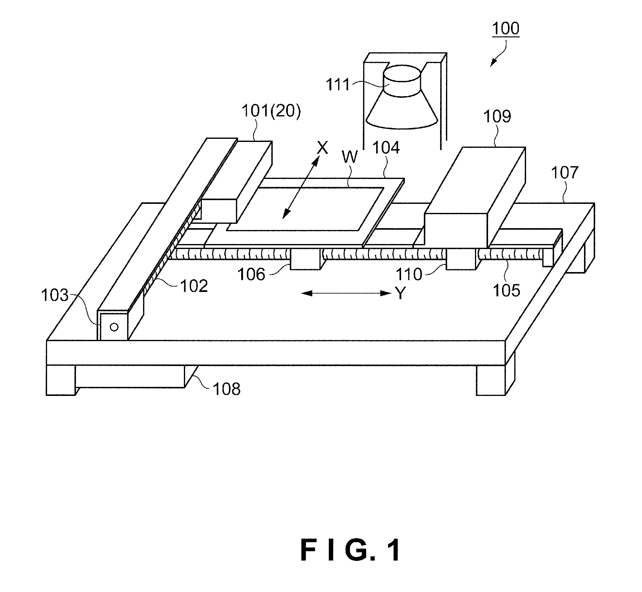
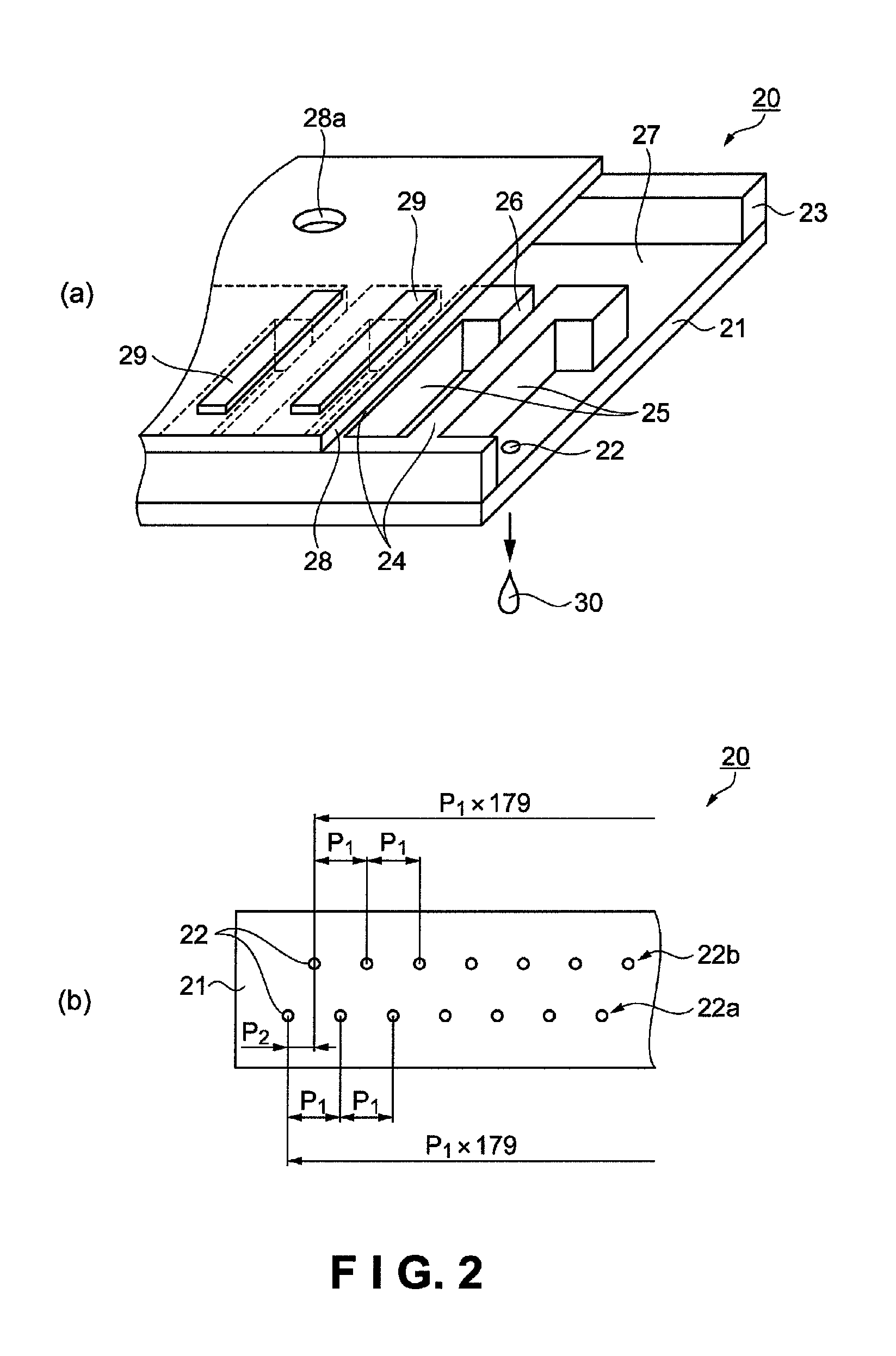
[0050]First, the configuration of the droplet discharge device according to the present embodiment will be described with reference to FIGS. 1 through 3. FIG. 1 is a schematic perspective view showing the configuration of a droplet discharge device. A droplet discharge device 100 discharges a liquid material as droplets onto a workpiece W as a discharge target and forms a film composed of the liquid material, as shown in FIG. 1. The droplet discharge device 100 comprises a stage 104 on which the workpiece W is placed, and a head unit 101 on which are mounted a plurality of droplet discharge heads 20 (see FIG. 2) for discharging the liquid material as droplets onto the positioned workpiece W.

[0051]The droplet discharge device 100 also comprises an X-direction guide shaft 102 for driving the head unit 101 in the sub-scanning direction (X-direction), and an X-direction drive motor 103 for causing the X-direction guide shaft 102 to rotate. Also included are a Y-d...

example 1

[0089]FIG. 8 is a schematic view showing the method for discharging a liquid material of Example 1. Specifically, the diagram is a schematic view showing the selection of drive waveforms for the nozzle rows and the arrangement of droplets in the film formation areas.

[0090]Nozzle numbers are assigned to the 180 nozzles 22 of a nozzle row 22a, as shown in FIG. 8. A method for selecting the drive waveforms to be applied to the nozzles 22 is shown as an example. The numeral 1 in the waveform selection indicates the drive waveforms A1, A2, etc. generated with the first system of timing in FIG. 7. Similarly, the numeral 2 indicates the drive waveforms B1, B2, etc. generated with the second system of timing, and the numeral 3 indicates the drive waveforms C1, C2 generated with the third system of timing. The circled numerals 1 through 3 in the diagram are hereinafter referred to as waveform selection system numerals 1 through 3.

[0091]The size and arrangement pitch in the X and Y-directions...

example 2

[0098]Next, the method for discharging a liquid material of Example 2 will be described, focusing on the differences from Example 1. FIG. 9 is a schematic view showing the method for discharging a liquid material of Example 2.

[0099]In the method for discharging a liquid material of Example 2, the allocation of drive waveforms of the first through third systems to the nozzle numerals in waveform selection 1 is different from that of Example 1, as shown in FIG. 9. Specifically, to state the sequence of drive waveform systems in the nozzle row 22a, the system numerals are 1, 2, 3, 2, 3, 1, 3, 1, 2 . . . (thereinafter repeating). As a result of this waveform selection, drive waveforms of the same system are not applied to adjacent nozzles 22. The number of nozzles 22 to which drive waveforms of the same system are applied (the number of nozzles 22 used) is set so as to be substantially equal with each system. The manner in which the drive waveforms weaken during droplet discharge is the...


PUM

PropertyMeasurementUnit
diameteraaaaaaaaaa
lengthaaaaaaaaaa
thicknessaaaaaaaaaa

Abstract

A method for discharging a liquid material includes performing a scan by moving a discharge target having a film formation area and a plurality of nozzles forming a nozzle row with respect to each other, and discharging a liquid material as droplets from the nozzles onto the film formation area by selectively applying one of drive waveforms generated using time division to an energy generation element of each of the nozzles in synchronization with the scan. The discharging of the liquid material includes applying a first drive waveform to a first nozzle of the nozzle row and a second drive waveform having a different discharge timing from the first drive waveform to a second nozzle of the nozzle row with the second nozzle being adjacent to the first nozzle, and changing a combination of the first and second drive waveforms selected from the drive waveforms at least once.

Description

CROSS-REFERENCE TO RELATED APPLICATIONS[0001]This application claims priority to Japanese Patent Application No. 2007-191677 filed on Jul. 24, 2007. The entire disclosure of Japanese Patent Application No. 2007-191677 is hereby incorporated herein by reference.BACKGROUND[0002]1. Technical Field[0003]The present invention relates to a method for discharging a liquid material containing a functional material, a method for manufacturing a color filter, and a method for manufacturing an organic EL element.[0004]2. Related Art[0005]Japanese Laid-Open Patent Application No. 2003-159787 discloses one known example of a method for discharging a liquid material containing a functional material, which is a method for discharging a liquid material containing a color filter material onto a substrate to manufacture a color filter.[0006]In the aforementioned color filter manufacturing method, a plurality of droplet discharge heads having a plurality of nozzles capable of discharging a liquid mate...

Claims


Application Information

Patent Timeline
Patent Type & Authority Patents(United States)
IPC IPC(8): B05D1/02
CPCB41J2/04525B41J2/04581B41J2/04588B41J2202/09B41J2/15B41J2/14233B41J29/393H05K3/125G02B5/201H05B33/10H10K71/135
Inventor MIYASAKA, YOICHI
Owner TOKYO ELECTRON LTD
Why Eureka
Try Eureka